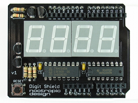
Easily add a four digit 7-segment display to your Arduino
Preparation
- Gather required tools: soldering iron, solder, wire cutters, and some tape for holding components in place while you solder them. I recommend wearing eye protection when you are clipping off the excess leads on components because the small pieces of metal can go flying in any direction.
- Check the parts list to make sure you have everything:
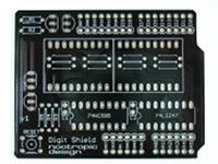
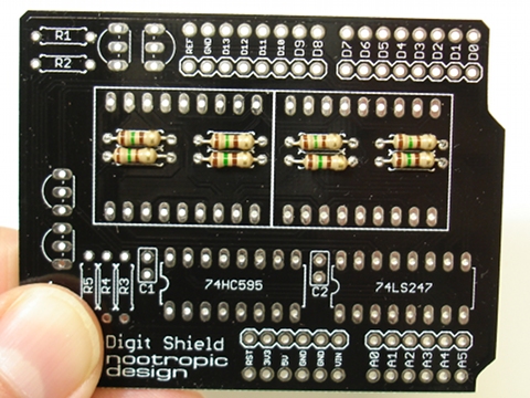
PCB
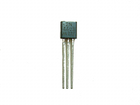
2N4403 PNP transistor (4)
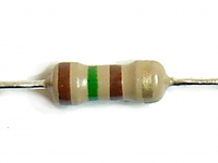
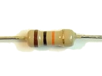
150 ohm resistor (8)
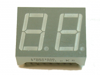
2 digit 7-segment display (2)
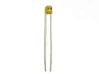
.1uF capacitor (2)
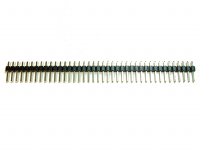
40-pin male header
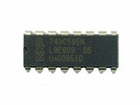
74HC595 shift register IC
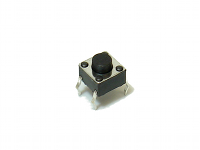
tactile switch
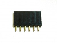
6-pin female header (2)
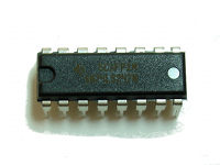
74LS247 LED display driver IC
10K resistor (5)
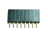
8-pin female header (2)
Step 1
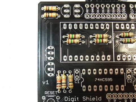
Insert the eight 150 ohm resistors into place. They are coded brown-green-brown-gold. IMPORTANT: Make sure that the resistors lay flat against the board.
Resistors are not polarized so you don’t have to worry about how they are oriented.
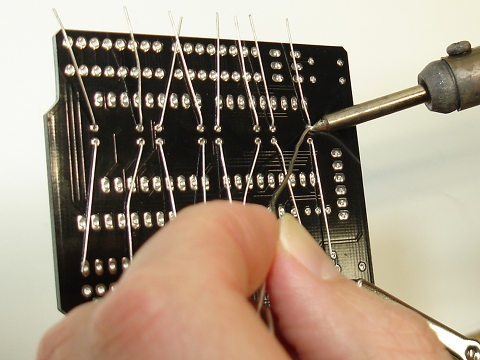
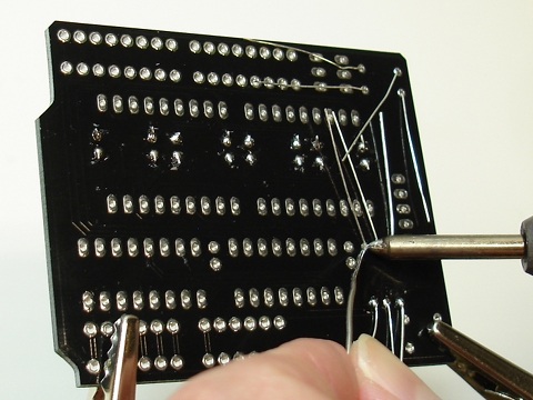
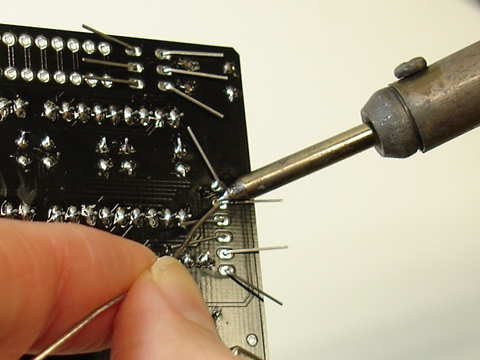
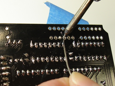
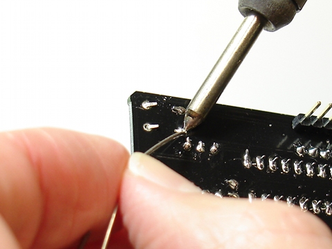
On the back of the board, solder the resistors by heating both the pad and the lead for a couple of seconds, then applying solder.
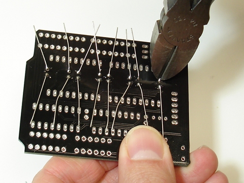
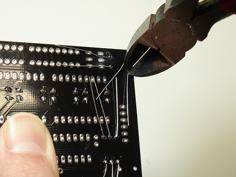
Using wire cutters, clip off the excess leads near the solder joint.
Step 2
Insert the five 10K resistors into positions labeled R1, R2, R3, R4, and R5. These resistors are color coded brown-black-orange-gold. Polarity does not matter.
Solder the resistors into place on the bottom of the board.
Clip off the excess leads.
Step 3
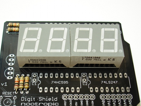
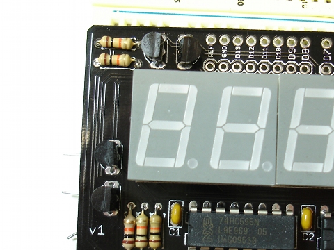
Place the LED displays on the board by inserting the pins into the holes. Make sure the decimal points are at the bottom!
If you have the red-orange LED displays, the 150 ohm resistors may prevent the LED displays from sitting perfectly flush on the board. But you should be able to position the displays such that they are aligned well.
Use some tape to keep the displays in place while you turn the board over and solder the pins. There are a lot of pins, but it should be quite easy.
Step 4
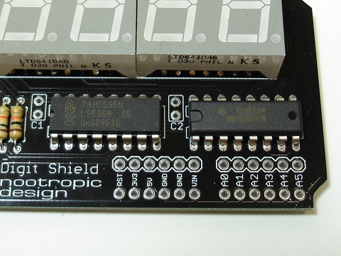
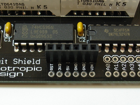
Solder the 74HC595 and 74LS247 ICs into place. Make sure you put the correct IC in the correct position according to the labeling.
Position each IC so the notch in one end of the socket is aligned with the notch drawn on the silkscreen (the left end).
If necessary, use some tape to hold the ICs flat against the board while you solder the pins on the bottom.
Step 5
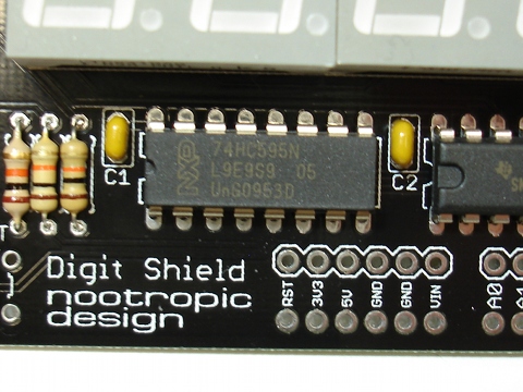
Place the two .1uF capacitors C1 and C2 in place next to the ICs.
These capacitors do not have polarity, so orientation does not matter.
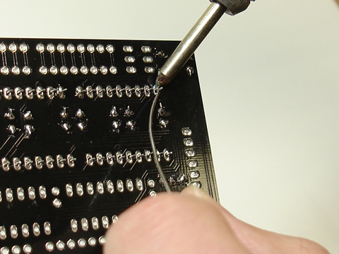
Turn the board over and solder.
As always, clip off the excess leads with wire cutters.
Step 6
Insert the four transistors into the board according to the outline of the transistor on the silkscreen. Make sure the flat side of the transistor is facing the correct position. It is OK if the transistors don’t sit flush with the board because the pins won’t quite allow them to.
Turn the board over and solder all the leads into place.
Clip off the excess leads.
Step 7
Female headers: it’s time to solder the female headers into place. The tricky part is getting them to stay aligned properly while you solder them on the bottom of the board.
Place one of the 6-pin female headers into position. Make sure it is in the “inner” row of holes, not the row of holes at the edge of the board. Use some tape to hold it in place — make sure it is vertical.
Turn the board over and solder it into place. I ususally start by soldering only one pin, then check to make sure the header is positioned correctly. If not, I gently heat the one pin again, and adjust the position of the header.
This will take time, but solder the rest of the headers into place.
Step 8
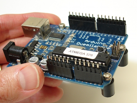
Male headers: these are easier than the female headers. Break the long male header strip into two 6-pin pieces and two 8-pin pieces. You may have some extras left over — they are a special gift for you.
Place these male headers into your Arduino.
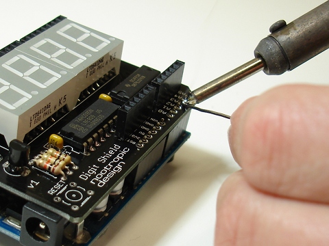
Put the Digit Shield board on top so the pins stick up through the holes on the edge of the board.
Solder them into place on the top of the board.
Step 9
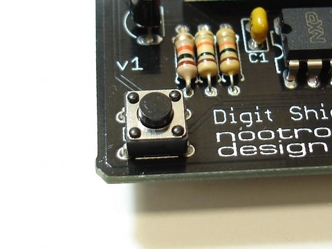
Insert the small tactile reset button into the lower left of the board. It should snap into place easily.
Turn the board over and bend the tabs down toward the board so they lay flat.
Solder it on the underside of the board.
Step 10
Bask in the glory of your success and have cool beverage of your choosing. Learn how to use the Digit Shield library on the main page and explore the projects on the projects page. Have fun!
Troubleshooting
If you’ve assembled the Digit Shield and it doesn’t seem to work, let’s ask ourselves some questions:
- Are you sure you’ve soldered everything together correctly? Double check your soldering to make sure you have no short circuits. Use a multimeter to help you determine if everything is connected. You can refer to the schematic available on the design page.
- Are you using the Digit Shield library correctly? Start with simple examples.