Preparation
- Gather required tools: soldering iron, solder, wire cutters, and some tape for holding components in place while you solder them. I recommend wearing eye protection when you are clipping off the excess leads on components because the small pieces of metal can go flying in any direction.
- Check the parts list to make sure you have everything:
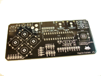
PCB
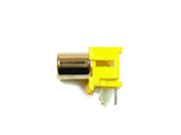
RCA jack (2)
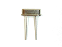
16MHz crystal
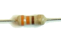
330 ohm resistor
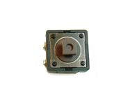
12mm tactile switch (5)
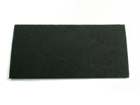
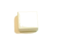
adhesive foam pad
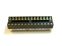
28-pin IC socket
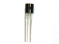
78L05 voltage regulator
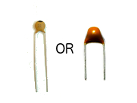
22pF capacitor (2)
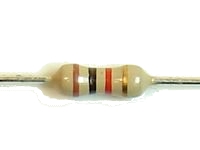
1K ohm resistor
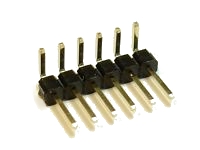
6-pin right angle header
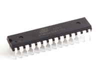
ATmega328 microcontroller IC
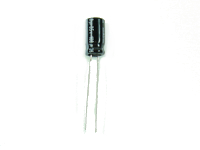
100uF capacitor
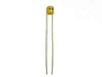
.1uF capacitor (2)
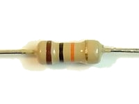
10K ohm resistor
white button cap (4)
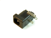
2.1mm barrel power jack
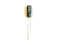
10uF capacitor
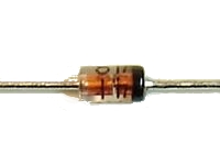
1N4148 diode (2)
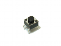
tactile switch
red button cap
Step 1
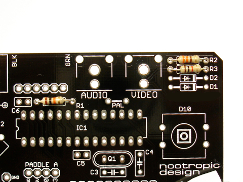
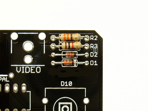
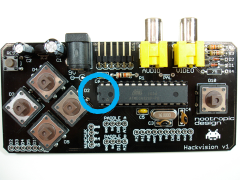
Insert resistors R1, R2, and R3 into place. R1 is just above the IC socket and is coded brown-black-orange-gold (10K ohms).
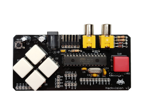
R2 and R3 are in the upper right of the board. Note that the labels “R2” and “R3” are not on the newer v2 version of the board.
R2 is 330 ohms and is coded orange-orange-brown-gold.
R3 is 1K ohms and is coded brown-black-red-gold.
Resistors are not polarized so you don’t have to worry about how they are oriented.
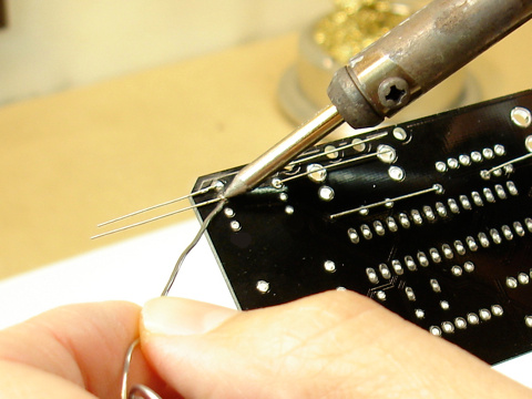
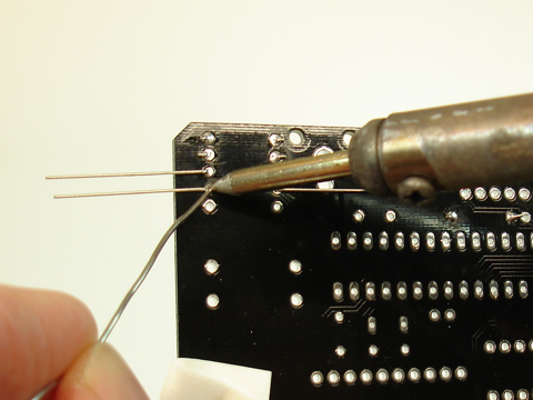
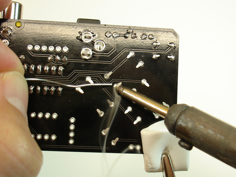
On the back of the board, solder the resistors by heating both the pad and the lead for a couple of seconds, then applying solder.
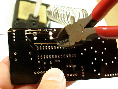
Using wire cutters, clip off the excess leads near the solder joint.
Step 2
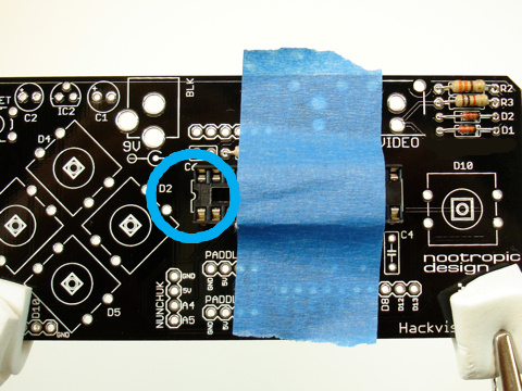
Insert the two diodes D1 and D2 into position in the upper right of the board. Both diodes are the same. Note that the labels “D1” and “D2” are not present on the v2 board. Diodes are polarized and must be oriented correctly. The black band around the end of the diode goes on the right side.
Solder the diodes into place.
Clip off the excess leads.
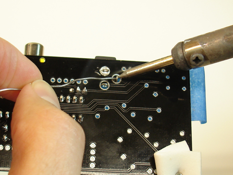
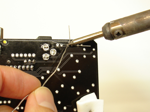
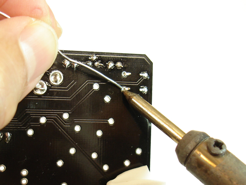
Step 3 (optional)
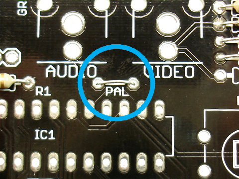
If you live in a country that uses the PAL television standard, then you will need to solder a wire jumper across the two contacts marked “PAL” just above the IC socket. You can use any sort of small wire like a lead that you just clipped off of a resistor or diode in the previous steps. This wire connects digital pin 12 to ground and tells the Hackvision firmware that it should initialize the TVout library with PAL parameters.
Note that if you connect this jumper, you cannot use digital pin 12 for anything. Setting pin 12 to output and setting it HIGH would cause a short circuit and damage the microcontroller.
Step 4
Solder the IC socket into place. Position the socket so the notch in one end of the socket is aligned with the notch drawn on the silkscreen. Use some tape to hold the socket flat against the board while you solder it into place. There are 28 pins to solder, but it’s not hard. Make sure you heat the pin and the pad for a couple of seconds before applying the solder.
Step 5
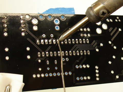
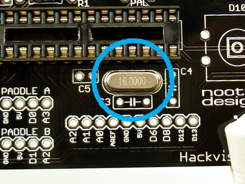
Insert the 16MHz crystal in to place just under the IC socket. Crystals do not have polarity, so orientation does not matter.
Turn the board over and solder.
As always, clip off the excess leads with wire cutters.
Step 6
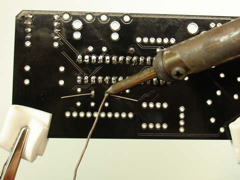
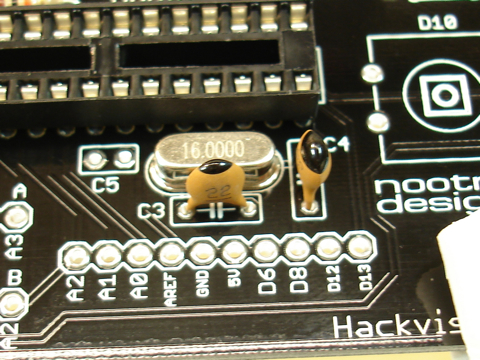
Position the two 22pF capacitors C3 and C4 near the crystal. These capacitors are not polarized so their orientation does not matter.
Turn the board over and solder.
Clip off the excess leads.
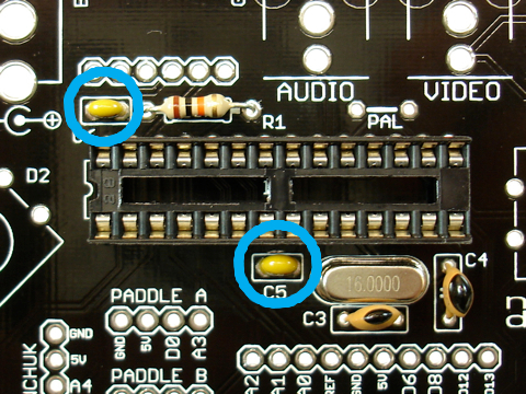
Step 7
Insert and solder the two tiny .1uF (or 100nF) capacitors C5 and C6 into place. C5 is on the left side of the crystal. C6 is above the IC socket.
Turn the board over and solder.
Clip off excess leads.
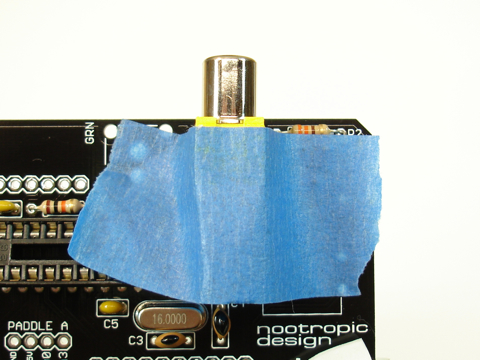
Step 8
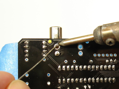
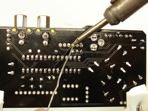
RCA jacks: position one of the jacks in place on the board and secure it with a piece of tape and turn the board over. If the plastic pegs on the bottom of the jack don’t seem to line up with the holes in the PCB, simply slide the jack toward the holes until the pegs drop into place. The holes for the leads are quite big so you will need to use a lot of solder to fill in the hole.
Hold your soldering iron on the lead and the metal pad around the hole (the annular ring) to heat them thoroughly. Then apply a generous amount of solder to the lead/pad to flood fill the hole. It can be tricky to get the pin/pad hot enough, so be patient and keep trying. Once it “gets started” you can fill the hole by pushing a lot of solder into the hole.
Repeat this process for the second RCA jack.
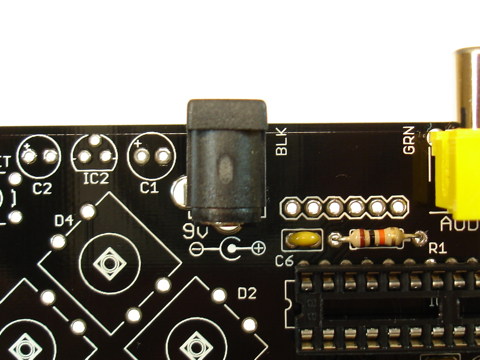
Step 9
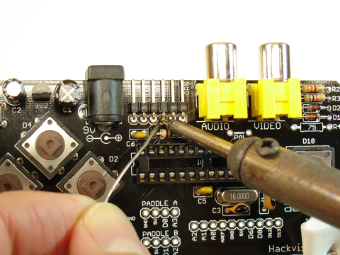
Power jack: this step is similar to soldering the RCA jacks. There are 3 leads on the connector. Use some tape to hold the jack into place in the 3 holes and turn the board over.
Just as you did with the RCA jacks, apply generous heat to the lead and annular ring at the same time, and push a generous amount of solder into the hole. Keep going until it is filled. Be patient, you can do it!
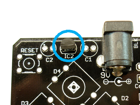
Step 10
Insert the 3-lead voltage regulator IC1 into place. Position the voltage regulator to match the outline on the PCB (flat side forward). You will need to bend the leads a bit in order to insert them into the holes.
Solder it on the bottom of the board.
Clip off excess leads.
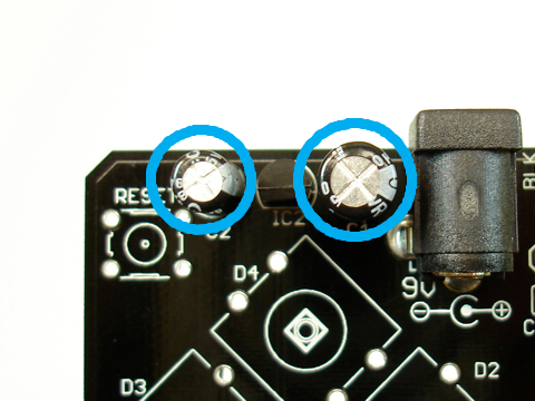
Step 11
Insert the two capacitors C1 and C2 into place next to the voltage regulator. C1 is a 100uF capacitor and is slightly larger than C2 which is 10uF. These capacitors are polarized and the longer lead is positive (the anode). Take care to insert the longer lead into the hole marked with a ‘+’.
Turn the board over and solder.
Clip off the excess leads.
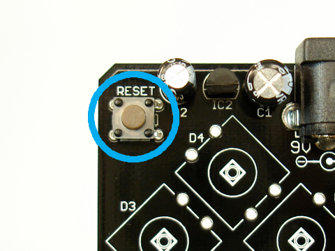
Step 12
Insert the small tactile button into the upper left of the board. This is the reset button. It should snap into place easily.
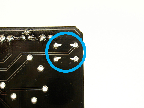
Turn the board over and bend the tabs down toward the board so they lay as flat as possible.
Solder it on the underside of the board.
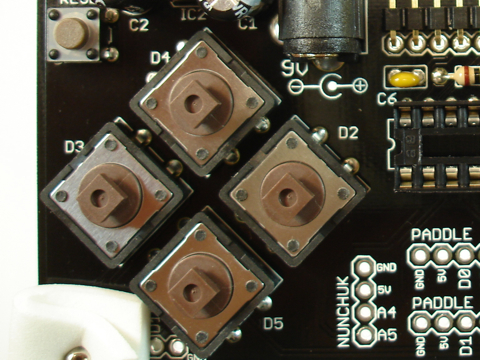
Step 13
Insert the 5 controller buttons: four directional buttons on the left side of the board, and the fire button on the right. They should snap into place nicely.
On the bottom of the board, bend the metal leads so they are more flat against the board.
Solder them into place.
Step 14
Programming header: insert the 6-pin right angle male header as shown with the “short” side of the right angle inserted into the board. The plastic part will be flat against the board.
To keep the header in place before we turn the board over, solder one of the contacts on the topof the board.
Turn the board over and solder the 6 connections on the underside of the board.
Step 15
Now it’s time to insert the ATmega328 IC into the socket. ICs can be sensitive to static electricity, so touch something grounded to ensure that you don’t have static electricity charge built up in your body. For example, a metal pipe or the screw on a electrical outlet wall plate.
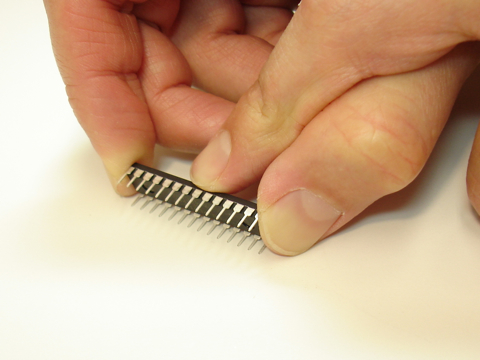
The pins on ICs are pointed outward from the chip a bit so we need to bend them inward so it will fit into the socket. Carefully bend the IC pins inward a bit by holding the chip against a flat surface.
When both rows of pins are bent inward, carefully insert the IC into the socket. Ensure that the notch on one end of the IC is aligned with the notch on the left end of the socket. Apply gentle pressure until the chip is seated in the socket. This can require quite a bit of pressure!
Step 16
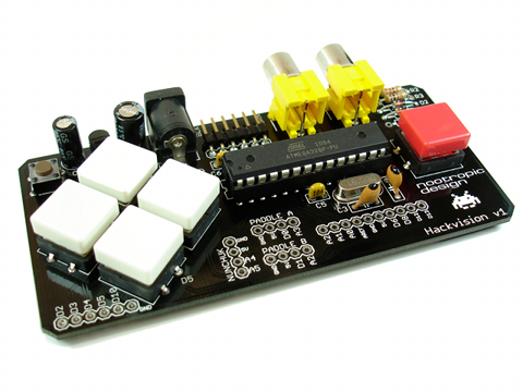
You are almost done. Put the button caps on the controller buttons by carefully snapping them onto the buttons.
Step 17
Let’s do a quick test before we apply the adhesive foam pad to the back. Try to avoid touching the back of the PCB during this test, especially the area around the crystal.
Connect your Hackvision to a television using ordinary RCA cables. One for video and one for audio. Since there is only one audio output, connect it to the left (white) connector on your TV. Many TVs will play the audio out both speakers if only the left channel is connected.
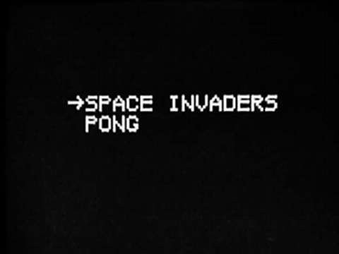
Then connect a 9V center-positive AC power adapter to your Hackvision. You should hear a “blink” sound from your TV and the game menu should appear.
If things don’t seem to be working, refer to the troubleshooting section below.
Step 18
Your kit comes with a foam pad with an adhesive backing. It’s important to insulate the bottom of the circuit board from your hands while the Hackvision is used. If you don’t insulate it and you touch the crystal or 22pF capacitor contacts, the chip will go haywire (this is not dangerous to you or the chip [probably]). If you don’t plan on soldering any more headers to the Hackvision (like for a nunchuk or paddles), then you can just trim the foam to the board shape and stick it on the back of the PCB. But if you want to do some hacking later on, then cut the foam to a shape that will leave the breakout soldering pads exposed on the back. Here is a template that you can print out and use.
Step 19
If everything seems to be working, bask in the glory of your success and enjoy a cool beverage. Now play some games and start thinking about what games you will design!
Troubleshooting
If you’ve assembled the Hackvision and it doesn’t seem to work, let’s ask ourselves some questions:
- Are you using an appropriate power supply? Hackvision requires a 9V DC supply with a center-positive pin. The inside contact on the 2.1mm connector is positive and the outside barrel is ground. An unregulated power supply is fine, but the polarity must be correct.
- Are you sure your TV is set to receive input from an external device? You will need to set it to display the signal from the appropriate inputs on the TV.
- No video? Do you hear any sound when you power on the Hackvision? When the main menu comes up, there should be a “blink!” sound. Try adjusting your volume and pressing the Hackvision reset button. If you hear the “blink!” sound and see no video, then you know that the Hackvision processor is actually running which means you’ve got a video connectivity issue.
- Have you tried another TV? It is possible that some TVs won’t work. Most TVs are very tolerant of the signal that the Hackvision produces.
- If your TV is old and you think it is non-standard, you can try installing the included 75 ohm resistor on the board. This may help some people whose TV does not have an internal 75 ohm resistor.
- Are you sure you’ve soldered everything together correctly? Double check your soldering to make sure you have no short circuits. Use a multimeter to help you determine if everything is connected. You can refer to the schematic available on the design page.