TV Blaster
Difficulty Level = 3 [What’s this?]
The Video Experimenter shield gives you new ways to interact with your TV. How many times did you wish you could blast someone or something on your TV screen? Now you can! This project lets you control a laser sight using a Wii nunchuk controller and fire an imaginary laser at the screen by pulling the trigger. Have fun.
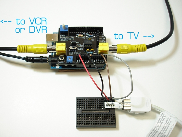
A Wii nunchuk can be connected to your Arduino using the I2C pins (analog pins 4 and 5). I use a little Wiichuck PCB to make it easy (these are available in the nootropic design store because we sell them for use with Hackvision). Don’t connect the Wiichuck PCB directly on the Arduino analog pins 2-5 because analog pin 2 is used by the Video Experimenter.
Data from the nunchuk is read using the Hackvision Controllers library.
The code is in the example “TVBlaster” in the TVout library for Video Experimenter.
Text and Graphics Overlay on Video
Difficulty Level = 2 [What’s this?]
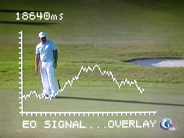
The Video Experimenter shield makes it easy to overlay text and graphics onto any composite video signal. Any source of composite video should work — video camera, VCR, DVD player, DVR, cable box, etc.
Video Experimenter projects require an enhanced version of the TVout library which can be downloaded here. All of the usual TVout drawing primitives can be used to add text or graphics to the screen. Here’s a video of a demo where I had the output of a VCR connected to the Video Experimenter input, then the Video Experimenter output connected to my TV.
The OverlayDemo sketch is in the TVout examples folder.
Here’s the OverlayDemo sketch source code. If you use a television with the PAL standard (that is, you are not in North America), change tv.begin(NTSC, W, H) to tv.begin(PAL, W, H).
#include <TVout.h>
#include <fontALL.h>

#define W 136
#define H 96

TVout tv;
unsigned char x,y;
unsigned char originx = 5;
unsigned char originy = 80;
unsigned char plotx = originx;
unsigned char ploty = 40;
char s[32];
int index = 0;
int messageLen = 32;
char message[] = "...OVERLAY TEXT AND GRAPHICS ON A VIDEO SIGNAL...OVERLAY TEXT AND GRAPHICS ON A VIDEO SIGNAL";
char saveChar;
byte ledState = LOW;

void setup()  {
  tv.begin(NTSC, W, H);
  initOverlay();
  tv.select_font(font6x8);
  tv.fill(0);
  drawGraph();
  randomSeed(analogRead(0));
}

// Initialize ATMega registers for video overlay capability.
// Must be called after tv.begin().
void initOverlay() {
  TCCR1A = 0;
  // Enable timer1.  ICES0 is set to 0 for falling edge detection on input capture pin.
  TCCR1B = _BV(CS10);

  // Enable input capture interrupt
  TIMSK1 |= _BV(ICIE1);

  // Enable external interrupt INT0 on pin 2 with falling edge.
  EIMSK = _BV(INT0);
  EICRA = _BV(ISC01);
}

// Required to reset the scan line when the vertical sync occurs
ISR(INT0_vect) {
  display.scanLine = 0;
}


void loop() {
  saveChar = message[index+22];
  message[index+22] = '\0';

  for(int x=6;x>=0;x--) {
    if (x<6) {
      tv.delay_frame(1);
    }
    tv.print(x, 87, message+index);

    for(byte y=87;y<96;y++) {
      tv.draw_line(0, y, 5, y, 0);
      tv.draw_line(128, y, 134, y, 0);
    }

  }

  message[index+22] = saveChar;
  index++;
  if (index > 45) {
    index = 0;
  }

  sprintf(s, "%ums", millis());
  tv.print(0, 0, s);


  if (plotx++ > 120) {
    tv.fill(0);
    drawGraph();
    plotx = originx + 1;
    return;
  }
  byte newploty = ploty + random(0, 7) - 3;
  newploty = constrain(newploty, 15, originy);
  tv.draw_line(plotx-1, ploty, plotx, newploty, 1);
  ploty = newploty;
}


void drawGraph() {
  tv.draw_line(originx, 15, originx, originy, 1);
  tv.draw_line(originx, originy, 120, originy, 1);
  for(byte y=originy;y>15;y -= 4) {
    tv.set_pixel(originx-1, y, 1);
    tv.set_pixel(originx-2, y, 1);
  }
  for(byte x=originx;x<120;x += 4) {
    tv.set_pixel(x, originy+1, 1);
    tv.set_pixel(x, originy+2, 1);
  }
}
Digit Shield Temperature Display
Difficulty Level = 1 [What’s this?]
The Digit Shield makes it trivial to add a numeric display to your project. I’ve used my simple LM34 temperature sensor in many projects, but this is the simplest. Here’s the LM34 sensor connected to analog input pin 0 on the Arduino, with the temperature displayed on the Digit Shield.
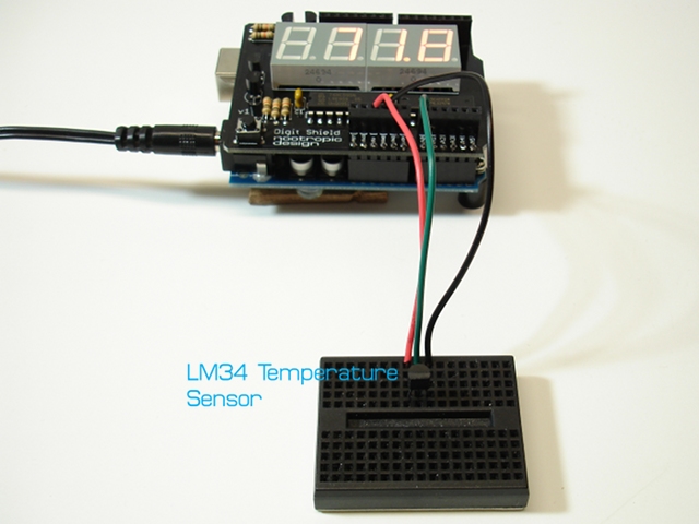
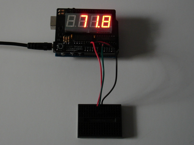
The code reads the sensor value, translates to millivolts, and then translates to a temperature (the sensor outputs 10mV per Fahrenheit degree). The Digit Shield library makes it so easy to display the temperature. Here’s the entire Arduino sketch:
#includefloat AREF = 1.1; void setup() { analogReference(INTERNAL); DigitShield.begin(); DigitShield.setPrecision(1); } void loop() { delay(500); int r = analogRead(0); int mv = (((float)r/1023.0) * AREF) * 1000.0; double t = mv / 10.0; DigitShield.setValue(t); }
Reaction Timer
Difficulty Level = 1 [What’s this?]
How fast can you press a button once a timer starts counting? Find out by attaching a button to your Arduino and the Digit Shield. A simple tactile button switch is connected to digital pin 8 and ground.
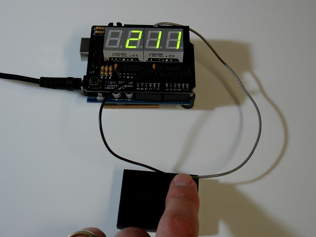
Press the button once to start the sequence. First the Arduino will wait a random amount of time between 2 and 5 seconds, then it will start counting milliseconds on the display. As soon as you see the numbers start, press the button again to stop the count. Then repeat: press the button again to clear the display and start the random wait before the numbers start counting again.
Here is the complete code:
#include <DigitShield.h>
#define BUTTON 8

unsigned long start, stop;

void setup() {
  randomSeed(analogRead(0));

  pinMode(8, INPUT);
  digitalWrite(8, HIGH);

  DigitShield.begin();
  DigitShield.setBlank(true);
}

void loop() {
  // wait until button press
  while (digitalRead(BUTTON) == HIGH);

  // turn off the display
  DigitShield.setBlank(true);

  // delay from 2 to 5 seconds
  delay(random(2000, 5000));
  start = millis();
  DigitShield.setBlank(false);

  while (true) {
    DigitShield.setValue((int)(millis() - start));
    if (digitalRead(BUTTON) == LOW) {
      stop = millis();
      break;
    }
  }

  DigitShield.setValue((int)(stop-start));
  delay(1000);
}
Asteroids Available for Hackvision
I’m very happy to announce Asteroids for Hackvision. This arcade classic gives you real arcade action written completely using Arduino. You can download it from the Hackvision games page, or order it pre-loaded on a Hackvision.
Game play is just like you remember:
- Shoot the asteroids and they break into smaller asteroids. Large asteroids are worth 20 points, medium 50 points, and small 100 points.
- Press the thrust button to move your ship forward. Unlike in real space, there is drag which slows your ship to a stop over time.
- Watch out for the flying saucer — it shoots in random directions and can crash into you. Shoot it for 500 points.
- If you are in real trouble, press the hyperspace button. This transports you to a different location, but that location may be very dangerous, too!
- When all the asteroids on a level are destroyed, a new level starts. Higher levels have more asteroids.
- You start with 3 ships, and get an extra ship every 10,000 points.
- At the end of the game you can enter your initials if you got one of the top 10 high scores. High scores are stored in EEPROM so they are not erased when power is off. Also, different games use different high score “files” in EEPROM, so your Asteroids scores won’t interfere with your Space Invaders scores, etc.
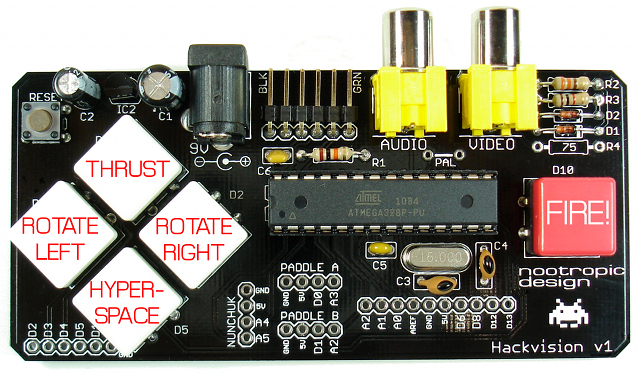
Here’s how the controls work:
Programming Details
void loop() {
  moveAsteroids();
  moveShots();
  getInput();
  moveShip();
  drawShip();
  drawSaucer();
  killed = detectCollisions();
  if (killed) {
    // pause and reset the ship...
  }
  drawExplosions();
  if (nAsteroids == 0) {
    // reset variables...
    newLevel();
  }
  if (remainingShips == 0) {
    gameOver();
    if (score > 0) {
      enterHighScore(1);
    }
  }
}
This game is all about collision detection. While the game is running, the code needs to detect the following collisions:
- collisions between your ship and asteroids
- collisions between the shots you fire and asteroids
- collisions between the saucer and your ship
- collisions between the saucer’s fired shot and your ship
- collisions between the shots you fire and the saucer
This sounds like a lot of work, but the ATmega328 has more than enough speed to perform all these computations many times per second. The key to these collision detections is using a “point in polygon” algorithm which determines whether a point is within the bounds of a polygon defined as a set of vertices.
The point-in-polygon algorithm is surprisingly short, but not very easy to understand. Here’s the function inPolygon which takes as arguments the number of vertices, an array of the X coordinates of the vertices, an array of the Y coordinates of the vertices, and the (x,y) coordinates of the point we are testing.
/*
 * This is the point-in-polygon algorithm adapted from
 * http://www.ecse.rpi.edu/Homepages/wrf/Research/Short_Notes/pnpoly.html
 */
boolean inPolygon(byte nvert, byte *xvert, byte *yvert, int x, int y) {
  char i, j;
  byte xvi, xvj, yvi, yvj;
  boolean inside = false;
  for (i=0, j=nvert-1; i<nvert; j=i++) {
    xvi = pgm_read_byte(xvert + i);
    xvj = pgm_read_byte(xvert + j);
    yvi = pgm_read_byte(yvert + i);
    yvj = pgm_read_byte(yvert + j);
    if ( ((yvi > y) != (yvj > y)) &&
         (x < (xvj - xvi) * (y - yvi) / (yvj - yvi) + xvi) )
       inside = !inside;
  }
  return inside;
}
Notice that the vertices are read from the AVR flash memory using the function pgm_read_byte(prog_uchar *pointer). I stored all the bitmaps and vertices in flash memory to conserve SRAM. This is critical when developing games on the ATmega328 since it only has 2K of SRAM. For more info on using flash memory, see the Arduino page on this subject.
Sound Design
With this game I took the sound design to a new level. The TVout library provides a simple tone(frequency, duration) function for generating tones using PWM on Arduino pin 11. This mechanism is very limiting when trying to create sounds for games. It’s easy to start a tone and have it play for a specified duration, but it’s difficult to create sound effects that require the rapid changing of frequency while still allowing the game to continue forward.
I needed a more dynamic mechanism to create the laser shot sound effect which requires the frequency to drop rapidly at a fixed rate of change so it didn’t sound too choppy. The solution was to take advantage of the VBI hook feature of TVout. VBI means Vertical Blanking Interval, and it’s the time period between the end of one screen frame and the beginning of the next frame. TVout draws at 60 frames per second (with NTSC), so there are 60 VBIs per second. The TVout function set_vbi_hook(void (*func)()) allows you to specify a function to be called at the end of every frame. This means you can specify some code to run 60 times per second at a perfectly uniform rate.
I created a function soundISR() to run at each VBI. This function checks to see if there is a sound playing, and a flag tells it whether the sound is the FIRE sound (laser shot) or EXPLOSION sound. Then the frequency is changed accordingly (e.g. for laser shot, decrement the frequency by 100 Hz) and the pin 11 PWM registers adjusted accordingly by the function setPWMFreq(unsigned int f). The sound effect is still initiated by calling tv.tone(freq, duration) and terminated by the TVout library, but my function modifies the frequency 60 times a second as needed. This led to a much better way of generating sound effects without interrupting game play.
Hacking Ideas
- Give yourself more lives. Find the line of code that sets remainingShips = 3 and change it.
- Enable “autofire” so you can hold the fire button down. Find the line in the code that says “uncomment for autofire”.
- Define your own bitmaps for the asteroids. What would you like to shoot? Also define vertices that define the bounding poloygon.
- Change the sound effects.
- Wire up an alternate controller using some awesome arcade buttons.
