Wireless Temperature Sensor
Difficulty Level = 5 [What’s this?]
UPDATE: I have re-done this project using simple 434MHz RF transmitter/receiver devices. Check out the new project!.
UPDATE: Also see this project for an easy way to display a temperature reading: Digit Shield Temperature Display.
I decided to explore the more advanced features of XBee radios by building a remote temperature sensor. You can get quite a bit of control over an XBee radio without a microcontroller at all. You can configure the radio to send sensor readings at particular intervals when it detects changes on certain input pins. For the details on configuring XBee radios, see the documentation at Digi International.
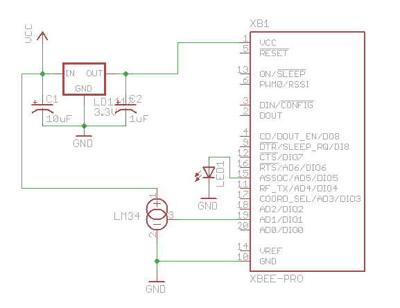
For this project, I configured the radio at the sensor end to read the analog input of pin 19 every 4 seconds and to send a sensor reading packet. Both the sender and receiver radios must be running the API firmware. This does not work if they are running the default AT firmware. And the “API” parameter is not the same as running the API firmware. You literally need to write a different firmware image to your radios using the X-CTU tool from Digi. I have Series 2 radios, so if you are using Series 1, you need to read the correct documentation for your radios and modify the code.
Input pin 19 on my sensor radio is configured (parameter D1) with value ‘2’ which means that it will read analog input, and the IO sampling rate (parameter IR) is set to ‘1000’ which sends a sample every 4096ms.
An LM34 temperature sensor outputs a variable voltage depending on the temperature. The mapping is extremely simple: 10mV for every Fahrenheit degree. So, at 72 degrees F, the output is 720mV.
Why did I choose pin 19? I started with pin 20, but I burned it out. The pins can only handle an analog input of up to 1.2V, and I think I may have sent too much into the pin. How? Well, let’s say it involved holding a cold Pepsi can on the circuit to cool off the temperature sensor, and I shorted out a connection with the can. Oops. I’m lucky I didn’t burn out the entire XBee chip.

Remote temperature sensor
Here is the circuit for the remote sensor:

Schematic for remote sensor circuit
For the receiving side, I used an Arduino with an XBee shield and a two digit LED display:
read more…
Hack-a-Sketch
Difficulty Level = 5 [What’s this?]
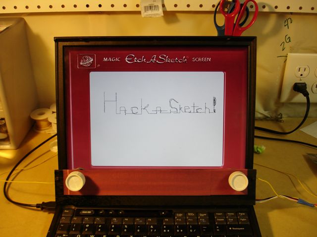
Here is a device I call the Hack-a-Sketch. The screen is a normal laptop (an old one), but it has real knobs which control the stylus on the screen.

The Hack-a-Sketch
An Arduino board reads the inputs from two potentiometers (the knobs), and sends the information via USB to a Processing sketch which displays the path of the stylus on the screen. This was extremely easy to build because the Arduino is just running the StandardFirmata firmware. No custom code on the board. The Processing sketch was surprisingly easy to write. Using this really did feel like using an Etch-a-Sketch.
Here’s the Hack-a-Sketch in action. Wait for the big finish where I erase the image…
How did I erase the drawing by shaking the computer? There’s a mercury switch hidden behind the panel holding the knobs. When the code senses shaking, the image is slowly erased. More shaking = more erasure.
read more…
LED Clock
Difficulty Level = 3 [What’s this?]
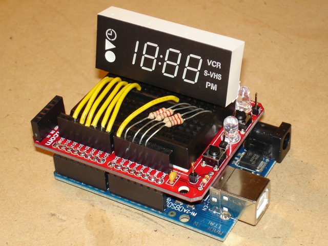
I harvested this LED clock display from an ancient VCR and wrote an Arduino sketch to drive the display. First I experimented with the leads to understand which leads controlled what behavior. There are 4 digits on the display and there are 4 corresponding leads for positive voltage to drive them (the Arduino pins connected with the resistors). Then there are 7 ground pins (the yellow wires) that correspond to the seven segments on each digit (well, the leftmost digit only has 2 segments). There’s also a pin for the colon but one of the LEDs is burned out.

ClockShield!
If you are unfamiliar with this multiplexing I’ve tried to explain, then study the code for the sketch. The array ‘number’ contains the information about what segments need to be on for each number. This might seem hard to understand at first, but I can guarantee an “ah ha!” moment when you get it.
// These are indexes into the groundPins array
#define MIDDLE 0
#define UPPER_L 1
#define LOWER_L 2
#define BOTTOM 3
#define LOWER_R 4
#define UPPER_R 5
#define TOP 6

int groundPins[7] = {2, 3, 4, 5, 6, 7, 8};
int digitPins[4] = {9, 10, 11, 12}; // positive voltage supply for each of the 4 digits
int ON = HIGH;
int OFF = LOW;
int number[10][7]; // holds information about which segments are needed for each of the 10 numbers
int digit[4]; // holds values for each of the 4 display digits

int hours = 12;
int minutes = 8;
int elapsedMinutes = 0;
int seconds = 0;

void setup()
{
  initNumber();

  for(int i=0; i < 7; i++) {
    pinMode(groundPins[i], OUTPUT);
    digitalWrite(groundPins[i], HIGH);
  }
  for(int i=0; i < 4; i++) {
    pinMode(digitPins[i], OUTPUT);
    digitalWrite(digitPins[i], LOW);
  }
}

void loop() {
  int n = 0;
  unsigned long time = millis() - (elapsedMinutes * 60000);
  seconds = (time / 1000);
  if (seconds > 60) {
    seconds = 0;
    minutes++;
    elapsedMinutes++;
    if (minutes >= 60) {
      minutes = 0;
      hours++;
      if (hours > 12) {
        hours = 1;
      }
    }
  }

  n = (hours * 100) + minutes;
  setDigit(n);

  for(int g=0; g < 7; g++) {
    digitalWrite(groundPins[g], LOW);
    for(int i=0; i < 4; i++) {
      if (digit[i] < 0) {
        continue;
      }
      digitalWrite(digitPins[i], number[digit[i]][g]);
    }
    delay(getDelay());
    digitalWrite(groundPins[g], HIGH);
  }
}

void setDigit(int n) {
  n = n % 2000;
  digit[0] = n % 10;
  digit[1] = (n / 10) % 10;
  if ((digit[1] == 0) && (n < 10)) {
    digit[1] = -1;
  }
  digit[2] = (n / 100) % 10;
  if ((digit[2] == 0) && (n < 100)) {
    digit[2] = -1;
  }
  digit[3] = (n / 1000) % 10;
  if (digit[3] == 0) {
    digit[3] = -1;
  }
}

int getDelay() {
  if (millis() > 10000) {
    return 0;
  } else {
    return (int) (((10000 - millis()) / 10000.0) * 125);
  }
}

void initNumber() {
  number[0][MIDDLE]  = OFF;
  number[0][UPPER_L] = ON;
  number[0][LOWER_L] = ON;
  number[0][BOTTOM]  = ON;
  number[0][LOWER_R] = ON;
  number[0][UPPER_R] = ON;
  number[0][TOP]     = ON;

  number[1][MIDDLE]  = OFF;
  number[1][UPPER_L] = OFF;
  number[1][LOWER_L] = OFF;
  number[1][BOTTOM]  = OFF;
  number[1][LOWER_R] = ON;
  number[1][UPPER_R] = ON;
  number[1][TOP]     = OFF;

  number[2][MIDDLE]  = ON;
  number[2][UPPER_L] = OFF;
  number[2][LOWER_L] = ON;
  number[2][BOTTOM]  = ON;
  number[2][LOWER_R] = OFF;
  number[2][UPPER_R] = ON;
  number[2][TOP]     = ON;

  number[3][MIDDLE]  = ON;
  number[3][UPPER_L] = OFF;
  number[3][LOWER_L] = OFF;
  number[3][BOTTOM]  = ON;
  number[3][LOWER_R] = ON;
  number[3][UPPER_R] = ON;
  number[3][TOP]     = ON;

  number[4][MIDDLE]  = ON;
  number[4][UPPER_L] = ON;
  number[4][LOWER_L] = OFF;
  number[4][BOTTOM]  = OFF;
  number[4][LOWER_R] = ON;
  number[4][UPPER_R] = ON;
  number[4][TOP]     = OFF;

  number[5][MIDDLE]  = ON;
  number[5][UPPER_L] = ON;
  number[5][LOWER_L] = OFF;
  number[5][BOTTOM]  = ON;
  number[5][LOWER_R] = ON;
  number[5][UPPER_R] = OFF;
  number[5][TOP]     = ON;

  number[6][MIDDLE]  = ON;
  number[6][UPPER_L] = ON;
  number[6][LOWER_L] = ON;
  number[6][BOTTOM]  = ON;
  number[6][LOWER_R] = ON;
  number[6][UPPER_R] = OFF;
  number[6][TOP]     = ON;

  number[7][MIDDLE]  = OFF;
  number[7][UPPER_L] = OFF;
  number[7][LOWER_L] = OFF;
  number[7][BOTTOM]  = OFF;
  number[7][LOWER_R] = ON;
  number[7][UPPER_R] = ON;
  number[7][TOP]     = ON;

  number[8][MIDDLE]  = ON;
  number[8][UPPER_L] = ON;
  number[8][LOWER_L] = ON;
  number[8][BOTTOM]  = ON;
  number[8][LOWER_R] = ON;
  number[8][UPPER_R] = ON;
  number[8][TOP]     = ON;

  number[9][MIDDLE]  = ON;
  number[9][UPPER_L] = ON;
  number[9][LOWER_L] = OFF;
  number[9][BOTTOM]  = ON;
  number[9][LOWER_R] = ON;
  number[9][UPPER_R] = ON;
  number[9][TOP]     = ON;
}
Now for the fun. The getDelay() method returns a delay based on how long the sketch has been running. First we start with a longer delay (125ms) between each segment so you can see visually how the digits are being rendered. Over the course of 10 seconds, we reduce the delay to 0. This way you can see exactly how quickly rendering the display causes you to see the digits without ficker even though each segment is being displayed separately! Cool, huh?
