The RGB Matrix Backpack is available from Adafruit and from the nootropic design store!
Building the RGB Matrix Backpack is easy and can be done in 30-60 minutes depending on your experience.
These instructions apply to both the matrix backpack for 16×32 panels as well as the new v2 version of the board for 32×32 panels.
Preparation
- Gather required tools: soldering iron, solder, wire cutters, and some tape for holding components in place while you solder them. I recommend wearing eye protection when you are clipping off the excess leads on components because the small pieces of metal can go flying in any direction.
- Check the parts list to make sure you have everything:
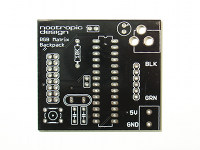
PCB
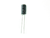
100uF capacitor
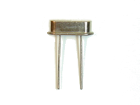
16MHz crystal
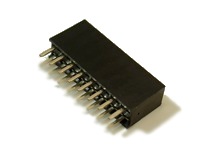
8×2 female header
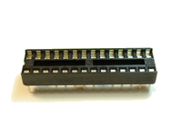
28-pin IC socket
22uF capacitor (2)
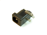
2.1mm barrel power jack
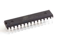
ATmega328 microcontroller IC
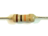
10K resistor
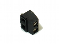
terminal block
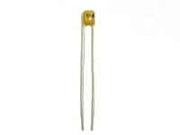
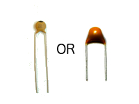
.1uF capacitor (2)
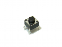
6mm tactile switch
6-pin right angle male header
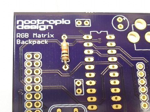
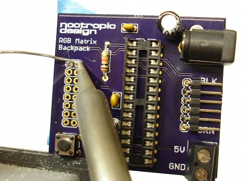
Step 1
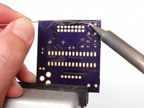
Insert the 10K resistor. It is coded brown-black-orange-gold. Resistors are not polarized so you don’t have to worry about how it is oriented.
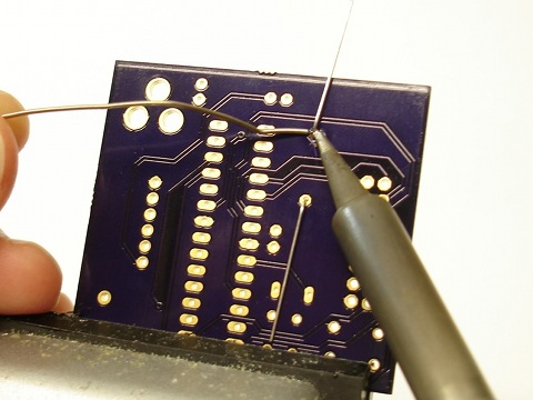
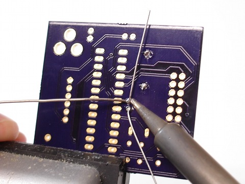
On the back of the board, solder the resistor by heating both the pad and the lead for a couple of seconds, then applying solder.
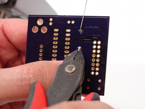
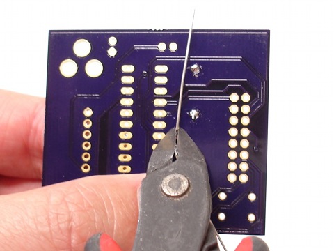
Using wire cutters, clip off the excess leads near the solder joint.
Step 2
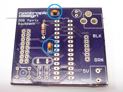
Insert and solder the two tiny .1uF (or 100nF) capacitors. They are marked with the code “104”.
Turn the board over and solder.
Clip off excess leads.
Step 3
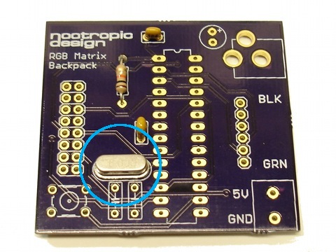
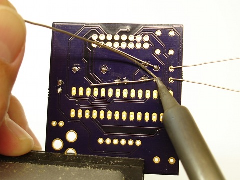
Insert the 16MHz crystal in to place. Crystals do not have polarity, so orientation does not matter.
Turn the board over and solder.
As always, clip off the excess leads with wire cutters.
Step 4
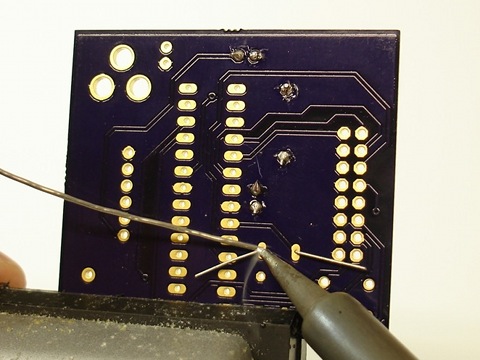
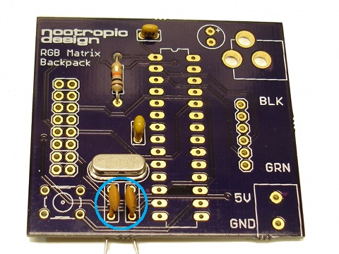
Insert the two 22pF capacitors just below the crystal. These capacitors are not polarized so their orientation does not matter.
Turn the board over and solder.
Clip off the excess leads.
Step 5
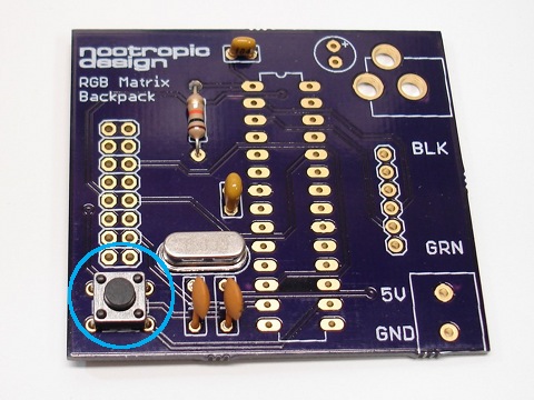
Insert the small tactile button into the lower left of the board. It should snap into place easily.
Solder it on the underside of the board.
Step 6
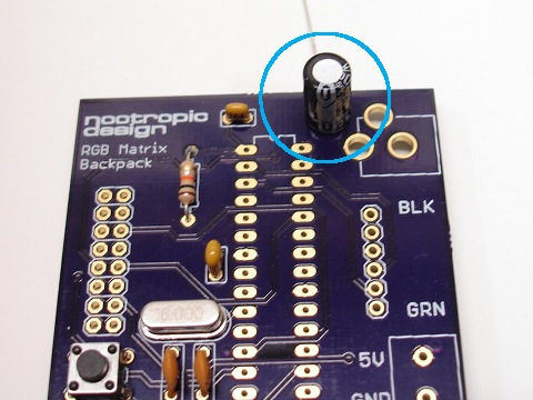
Insert the 100uF electrolytic capacitor into the board. This capacitor is polarized and the longer lead is positive (the anode). Take care to insert the longer lead into the hole marked with a ‘+’.
Turn the board over and solder.
Clip off the excess leads.
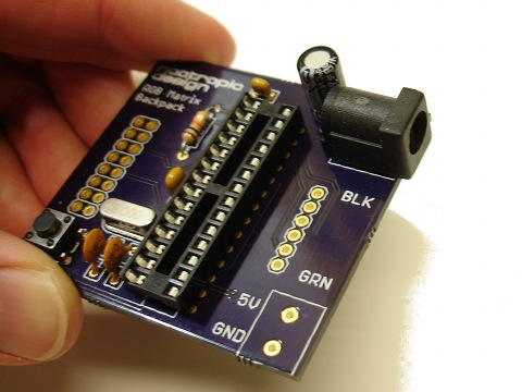
Step 7
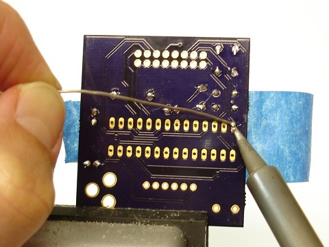
Solder the IC socket into place. Position the socket so the notch in one end of the socket is aligned with the notch drawn on the silkscreen. Use some tape to hold the socket flat against the board while you solder it into place. There are 28 pins to solder. Make sure you heat the pin and the pad for a couple of seconds before applying the solder.
Step 8
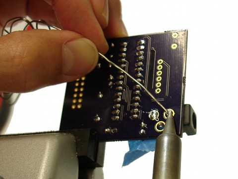
Power jack: there are 3 leads on the connector. Use some tape to hold the jack into place in the 3 holes and turn the board over.
Apply generous heat to the lead and annular ring at the same time, and push a generous amount of solder into the hole. Keep going until it is filled. Repeat for the other two connections. Be patient, you can do it!
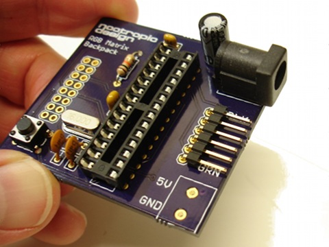
Step 9
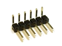
Programming header: insert the 6-pin right angle male header as shown with the “short” side of the right angle inserted into the board. The plastic part will be flat against the board.
Use some tape to keep the connector in place.
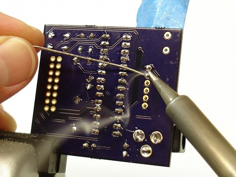
Turn the board over and solder the 6 connections on the underside of the board.
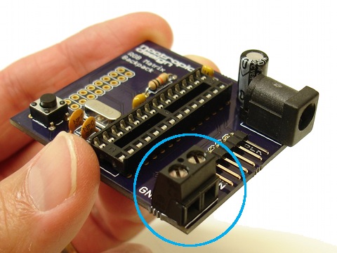
Step 10
Place the terminal block on the board, making sure that the terminal connection openings are facing the outside of the board.
Hold the block in place with some tape and turn the board over.
Solder the two connections.
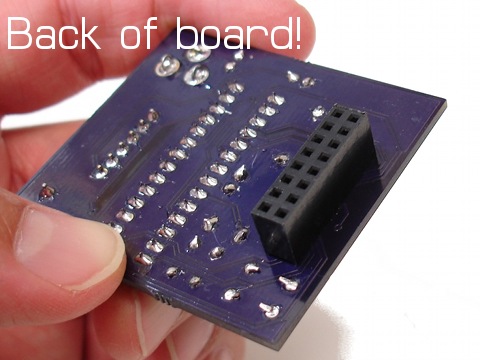
Step 11
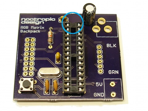
IMPORTANT! The 8×2 female header connector goes on the BACK of the board, not the top. Hold the connector in place with some tape.
Turn the board over and solder the connections on the FRONT of the board.
Step 12
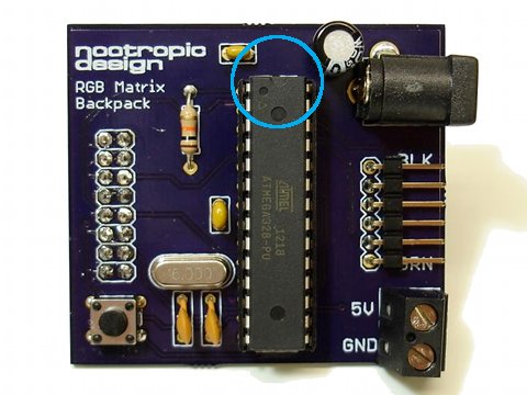
Now it’s time to insert the ATmega328 IC into the socket. ICs can be sensitive to static electricity, so touch something grounded to ensure that you don’t have static electricity charge built up in your body. For example, a metal pipe or the screw on a electrical outlet wall plate.
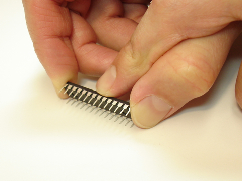
The pins on ICs are pointed outward from the chip a bit so we need to bend them inward so it will fit into the socket. Carefully bend the IC pins inward a bit by holding the chip against a flat surface.
When both rows of pins are bent slightly inward, carefully insert the IC into the socket. Ensure that the notch on one end of the IC is aligned with the notch on the left end of the socket. Apply gentle pressure until the chip is seated in the socket. This can require quite a bit of pressure!
Step 13
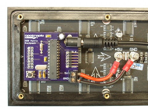
Connect the board to your Adafruit matrix panel. The 16×32 panel is shown here (click image to enlarge) but the 32×32 panel is similar. The 8×2 connector is for the LEFT connector on the panel. Connect the panel’s power connections to the terminal block, paying close attention to the polarity.
Connect a 5V regulated power supply that can source 2A. DO NOT use a 9V supply, or an unregulated 5V supply.
Step 14
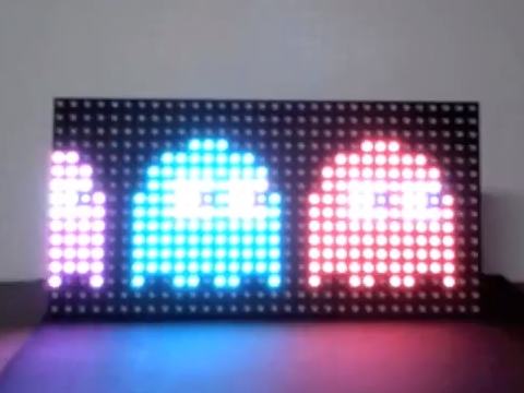
The ATmega for 16×32 panels is preloaded with a nice animation demo, and you should see vibrant colors and smooth animation. The v2 board for 32×32 panels is preloaded with the “plasma_32x32” example sketch. Bask in the glory of your success and have a beer. If you don’t drink or are too young to drink, have a piece of candy or something.
Learn how to program the panel using the Adafruit matrix tutorial page. Of course, you can skip all the wiring steps with the Arduino, because you have your own Arduino connected right to the panel!
Troubleshooting
If you’ve assembled the RGB Matrix Backpack and it doesn’t seem to work, let’s ask ourselves some questions:
- Are you using the Adafruit 16×32 or 32×32 matrix? This backpack is not designed to work with any other panels.
- Are you using a 5V regulated power supply that can provide at least 2A of current?
- Are you sure you’ve soldered everything together correctly? Double check your soldering to make sure you have no short circuits. Use a multimeter to help you determine if everything is connected. You can refer to the schematic available on the design page.