The nootropic design Video Experimenter shield uses some pretty advanced features of the Arduino’s ATmega328 microcontroller. One downside of this is that you can’t use the Video Experimenter shield on an Arduino Mega. Why? Well, the designers of the Arduino Mega didn’t connect a lot of the ATmega1280/ATmega2560 pins to headers on the board so that you could use them! And, as it turns out, the pins with key features utilized by the Video Experimenter are not connected to anything!
To perform video overlay, the Video Experimenter relies on an input capture pin (to capture the exact time that the pin has changed state). Even though the ATmega1280/ATmega2560 has 4 input capture pins, none of them are connected!
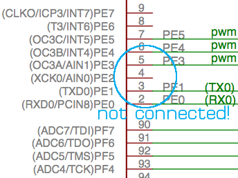
And to capture video images in the Arduino’s memory, Video Experimenter uses the analog comparator in the chip. But the AIN0 pin for the analog comparator is not connected! What were the Arduino Mega designers thinking?
Fortunately, there is the Seeeduino Mega. The guys at Seeed Studio broke out nearly all the pins on the ATmega1280 so that you can use them. I love the Seeeduino Mega because it provides so many pins on a rather small board.
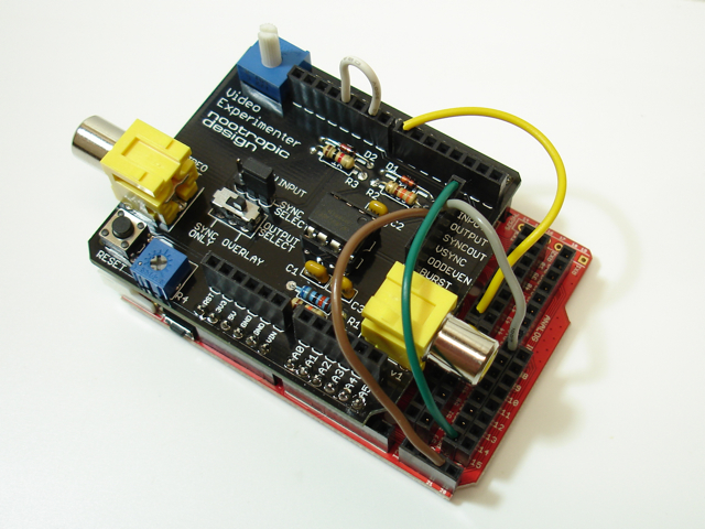
Simply make 5 connections with jumper wires and you can use the Video Experimenter on the Seeeduino Mega. No code changes necessary!
Here are the connections to make:
11 to 9 (white wire in picture above)
7 to 29 on the Seeeduino Mega (yellow wire)
INPUT pin on the Video Experimenter to PE2 on the Seeeduino Mega (green wire)
SYNCOUT pin on the Video Experimenter to PD4 on the Seeeduino Mega (gray wire)
VSYNC pin on the Video Experimenter to 21 on the Seeeduino Mega (brown wire)
Now you can use the Video Experimenter with an Arduino that has a more powerful processor. It really helps to have 8K of SRAM instead of 2K. Now you can do text and graphics overlay with higher resolutions, like 192×128. Have fun!


Agreed — the Seeedunio Mega is mega better than the Mega. Their first Mega was their second board to put on the extra row of aligned headers for D8-13+AREF+AGND. Something that the Arduino team hasn’t been able to do in what,… five tries? The Seeeduino Mega is a big win over the original.
Glad to hear that you found them, and that you’re a fan too. That’s what happens when actual engineers engineer.
I am experimenting with blind sensory substitution …..The vOICe… which currently uses Android phone hardware to produce audio scapes for blind users.
A full height video frame produces a massive chorded sound picture which with practice produces a sensory image.
However , a restricted height image, eg 20 lines of pixels, produces a very easily learnable radar scan type of signal. This enables door location, reaching and grasping, domestic and street mobility, at a very early stage of rehabilitation.
In actual operation, this restricted scan has been compared to the swishing of a white cane, even sounding pretty similar. This is a very worthwhile and Public Domain avenue for projects. The Video Experimenter board sounds ideal for this work.
Score one for Open Hardware!
To see The vOICe in action, London, 20 Nov. 2011, look up http://www.youtube.com/watch?v=ycw1cV0e7Gg
The user is burdened with unreliable USB spy glasses , cabled to a PC tablet in backpack.
The full height soundscape is being displayed.
Now imagine the system pared down to a horizontal slot eg 10 lines of pixels, without much of the academic software built into the vOICe system.
This would give collision avoidance immediately, and by nodding the user can vertically scan the whole scene.
Try an experiment. Cut a narrow slot in a shoe box and study the world through it. Imagine this as a sonified display .
With a NTSC camera, gated down to 10 lines output, snapshot capture and one-second sonification appears quite feasible with Arduino variants.
The whole system could be on one board, hat or frame mounted.
I have purchased and built the experimenter board and I am now wanting to use it with the Seeeduino R3 board. I have tried to translate your instructions for adapting the Seeeduino Mega but do not know the equivalent pins on my board. Please can you put up a guide to getting video experimenter working with the Seeeduino R3 (which I do hope is possible).
Thanks
I don’t know what a Seeeduino R3 is … Google did not find anything. Do you mean a Seeeduino V3.0? If so, it is Arduino compatible, so the Video Experimenter will work without having to do anything special. Any Arduino compatible board with an ATmega328 will work.
Hi Michael,
Thanks for your prompt reply. Yes I did mean the V3.
Thanks to your confirmation that it has all the right connections, I shall now plug it all together with confidence and start experimenting.Cheers.
Hi,
What is the green wire for? I want to capture video frames and communicate over I2C at the same time, and it seem to create problems for me…
The green wire is the input pin for sampling the voltage. I2C is going to be very hard while doing video stuff. See the forum for further discussion.
Hi
Thanks for the hint about visiting forum, I have read about the trick with set_vbi_hook(). However I still have a concern about I2C because of the brown wire connected to SCL. What is the brown wire for?
Hi again,
I’ve solved the problem by soldering the brown wire to pin D18 (TX1) and by changing
EIMSK = _BV(INT0);
EICRA = _BV(ISC01);
to
EIMSK = _BV(INT3);
EICRA = _BV(ISC31);
and
ISR(INT0_vect) {
to
ISR(INT3_vect) {
Now everything works fine (I2C and frame capturing). Thanks for the great product!
Ok, makes sense. The brown wire is the vertical sync pin of the LM1881 and is connected to external interrupt 0, but you moved it to external interrupt 3 to avoid the SCL conflict. Good job!
HI,
Seeeduino Mega V3.0 is an Arduino board based on ATmega2560, you confirm it can work with the shield?
Regards
It should work, Lemorlenny.