Many of our Defusable Clock customers use the device in Airsoft competitions where participants must find the device and defuse it before the timer expires. A great thing to do in these games is to trigger a loud siren or smoke grenade when the timer reaches 00:00. The new version V2 of the clock has a connections for such a trigger and we are now selling relay modules in the nootropic design store.
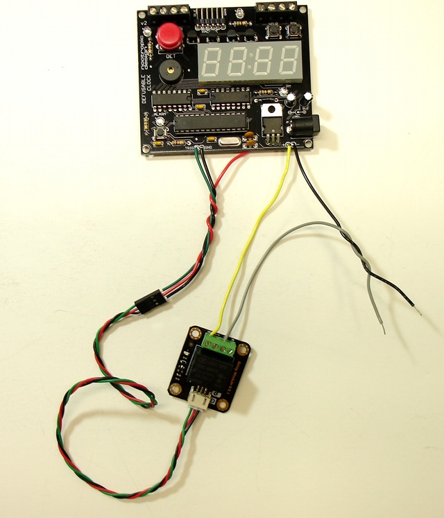
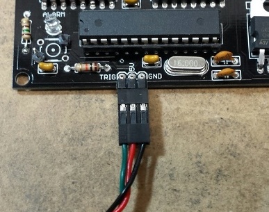
Below is a picture that shows how to connect a relay. The red wire is 5V and if you have an older kit it needs to be soldered to the output pin of the voltage regulator. It then connects to the 5V red wire on the relay module. The 5V output is the rightmost pin of the voltage regulator when looking at the front of the board. The green wire is the trigger connection and goes to the green wire on the relay module. The trigger ground connection is the black wire going to the relay module.

UPDATE: there is now a 5V pad next to the trigger and ground pads that you can use:

To send 9V to your destination device like a siren or smoke grenade, connect a wire to the + connection near the power connector, and a ground wire to the – connection. These are shown as yellow and black wires in the picture. This assumes you have a 9V input voltage to the clock. If you are using a different voltage like 12V or a 7.4V lipo battery, that’s fine. This is the voltage available on the + connection.
The black ground wire connects directly to your device. The positive voltage (yellow wire) connects to the relay module terminal marked “COM” (for “common”). The gray wire in the picture is connected to the relay terminal marked “NO” (for “normally open”) and this wire is the positive voltage to your siren or smoke grenade or whatever.
When the countdown reaches 00:00, the trigger voltage (green wire) will cause the relay to close and connect the 9V yellow wire to the gray wire, thus providing 9V to your external device for a duration of about 2.5 seconds while the clock goes through the “detonation” sequence. If you want power to be disconnected when the countdown reaches 00:00, connect the gray wire to the terminal marked “NC” (“normally closed”) instead.
Have fun, and as always, stay out of trouble!

Hi I recently bought the clock kit from cool components in the UK but turned out was v1. Is V2 for sale in the |UK?
Martin, I actually just sent a shipment of v2 boards to Cool Components yesterday. There is not much difference with V2 — just the addition of the breakout pads for attaching a relay.
on the relay switch that order I noticed in the photo thr lead with the three wires red, green
and black female lead, Question do you sell the male lead shown in the diagram with the relay to
the clock trigger?
No, only the wires on the relay are included. See http://nootropicdesign.com/store/index.php?main_page=product_info&cPath=3&products_id=44
But if you order and want a 3-pin connector soldered to the board just say so. The board connections are now 3 pads right next to each other (trigger, 5V, GND).
Hi, I recently completed the clock and would like to incorporate the relay. How do I use the relay with a different voltage? And what is the maximum volts and amps through the relay?
Do the trigger, ground and positive complete the relay input/control on the 9v side and is the rest of the wiring simply for taking power from the same 9v source. I didn’t read ahead but used those headers as the connection point for a 9v battery terminal.
Can I then use a separate 12v power source with the positive in the COM and out of the NO?
Many thanks.
The relay specs are http://www.dfrobot.com/wiki/index.php?title=Relay_Module_(Arduino_Compatible)_(SKU:_DFR0017). It can switch 24V up to 10A.
The 5V, trigger and GND connections are for operating the relay. You can connect a separate power source through the COM and NO terminals to control a completely different power source. In that case ignore the connections to 9V and GND near the voltage regulator. In this example I gave, I was using the relay to control a 9V power source (drawn from the board itself), but you can use a different power source. Think of the COM and NO connections as an ordinary switch that you want to control.
Hello Michael,
I have a V1 board, without the TRIG/GND pads. Can you recommend any pins on the board that can be used for the TRIG output? I will most likely connect to an Arduino or Raspberry Pi digital I/O port, so I just need +5V during detonation and 0V otherwise, or vice versa.
Thanks,
— Paul
Yes, there is one pin available for use: A0. Just google for a diagram of the ATmega328 chip so you know which one it is. You will have to solder a wire to the pin directly. Let me know if you have any problem.
Michael,
Looks like pin 23. I’ll probe it to make sure.
Thanks for the assistance and quick response!
— Paul
Hello… I would like to buy “Game Timer Pro + keypad + DFRobot Relay Module” for Airsoft so we have more fun.
All I wanna know is when I get the stuff and connect all parts together (board with defuse wires, keypad and relay module) will I be able at the same time to use defusing wires and keypad(to defuse the trap)+relay module to ignite firecracker or firework (depend on the surrounding and type of game).
You can choose to defuse by keypad or by a wire, but not both at the same time unless I customize the code for you.