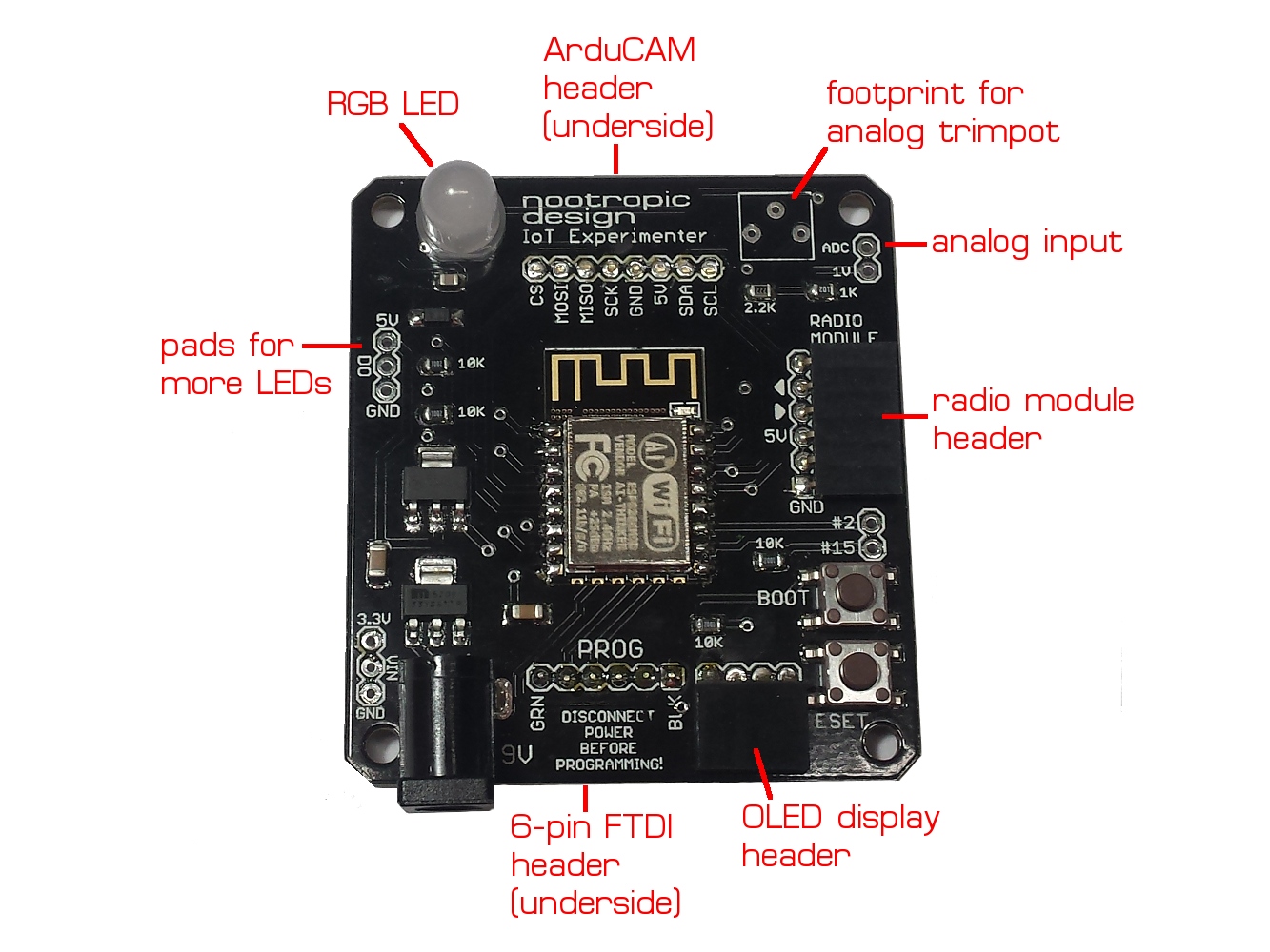
Introducing the IoT Experimenter ESP8266 Development Board
Like many other hardware hackers, I fell in love with the ESP8266 Wi-Fi microcontroller as soon as I started using it. It is fast, has plenty of memory, has Wi-Fi networking, and can be programmed in a number of ways. Lots of people like the Lua firmware, but I prefer to use the ESP8266 core for Arduino because I can use all the great libraries already built for Arduino.
I’m also working with LoRa radio technology. Several small Arduino-based boards are available for experimenting with LoRa: Moteino and Anarduino MiniWireless have LoRa capable boards that are easy to use. They both have the standard 6-pin serial connection for easy programming. What I really wanted to do is combine long range radio technology with Wi-Fi connectivity, so I designed an ESP8266 Development board that allows for easy connection of a LoRa radio module. While I was at it, I also included connectivity for an OLED display, ArduCAM camera module, and included a nice big PL9823 RGB LED that can be controlled just like WS2812 LEDs.
IoT Experimenter ESP8266 development board
There’s also connection for analog input with a voltage divider to scale voltage down to the 1V ranged required by the ESP8266. The board has 2 voltage regulators: a 3.3V one for the ESP8266, and a 5V regulator for powering the RGB LED and to provide power to the radio module header. If you are wondering how I drive a 5V LED with 3.3V logic from the ESP, a diode in line with the LED’s power supply drops the VCC low enough for 3.3V logic to work reliably. I learned that clever trick from this Hackaday article. If you want to connect a strip of WS2812 LEDs, there are pads for that, too.
The TX/RX serial lines for the radio module and ESP8266 are connected together for simple serial communication. This makes it easy to build a simple radio to Internet gateway. See my project Solar-Powered LoRa Weather Station for a good example of this approach. Also, this header can be used for any kind of radio (not just LoRa) that has a 6-pin header with the standard FTDI pinout. In fact, it doesn’t have to be a radio at all! Communication with any serial device might be just what you need.

Radio module attached to IoT Experimenter
The ArduCAM camera module for Arduino works great with the ESP8266 (here is the library) so I can make surveillance cameras with this board. The 8-pin female header for the camera is on the underside of the board and the camera fits great right on top of the board.
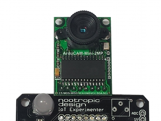
ArduCAM module attached to IoT Experimenter
I also love those cheap I2C OLED displays. They come in several colors and are only a few dollars. So I added a header for that also. It’s great for debugging, and when you are done, just pull the display off.
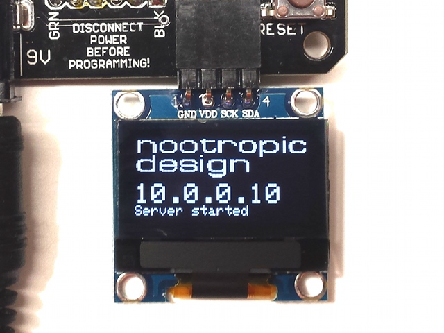
OLED display attached to IoT Experimenter
The PL9823 RGB LED can be controlled using any WS2812 library, like the Adafruit NeoPixel library. This big 8mm LED looks great. Make it any color you want!

RGB LED
This board has proven really useful for me in several projects, and I’m probably going to offer it as a product. Hope you like it, and if you are interested, let me know.
Wi-Fi IoT Electrical Outlet: Turning on a Coffee Maker Remotely
Project source code at GitHub: iot-wifi-outlet
They say necessity is the mother of invention, and there’s no question that the need to turn on my coffee maker while still in bed is a necessity. I don’t want to wait for my coffee to brew after I go down to the kitchen in the morning. I want my coffee ready as soon as I get there. It’s not that I’m impatient, I just have lots of electronics work to do, right?
Obviously, I needed a solution that would allow me to start my coffee brewing from my phone which I keep at my bedside. This is a great example of a problem in need of an IoT (Internet of Things) solution. The coffee maker is a thing I want to control from the Internet.
I’m the only one in my house that drinks coffee, so I have a simple single-serving coffee maker that I like to set up the night before. To brew, there is a mechanical button on the side that turns on the heating element and then “pops out” after the brewing process. If there is no power supplied to the coffee maker, this button can still be pressed in, and when power is supplied, the brewing will start. All I needed is a way to turn on the AC mains power to the coffee maker.
Building an Wi-Fi Enabled Electrical Outlet
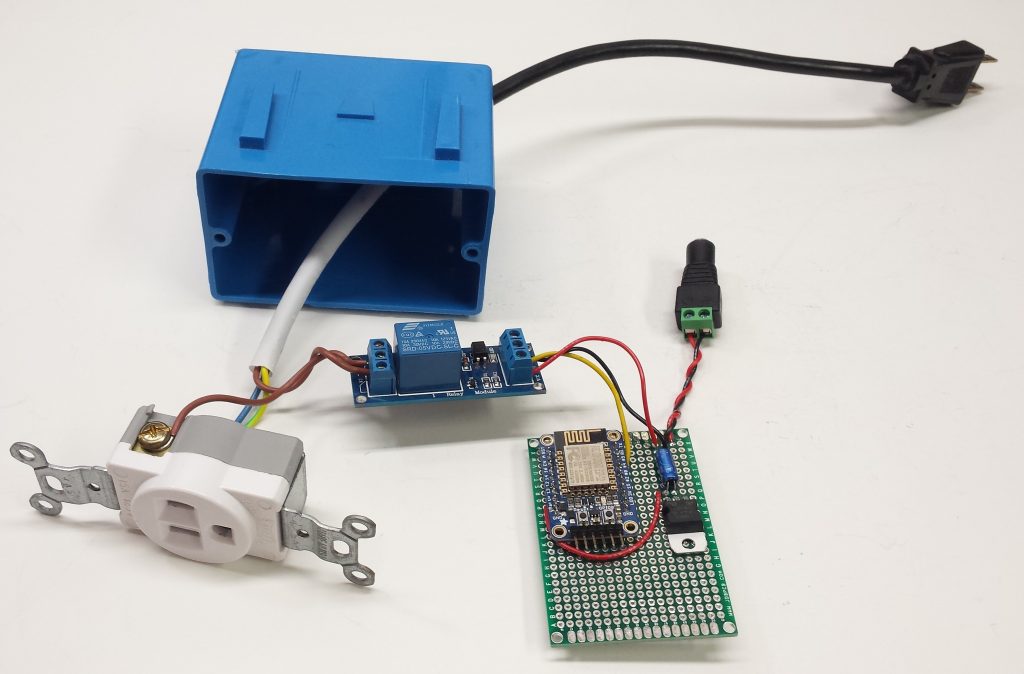
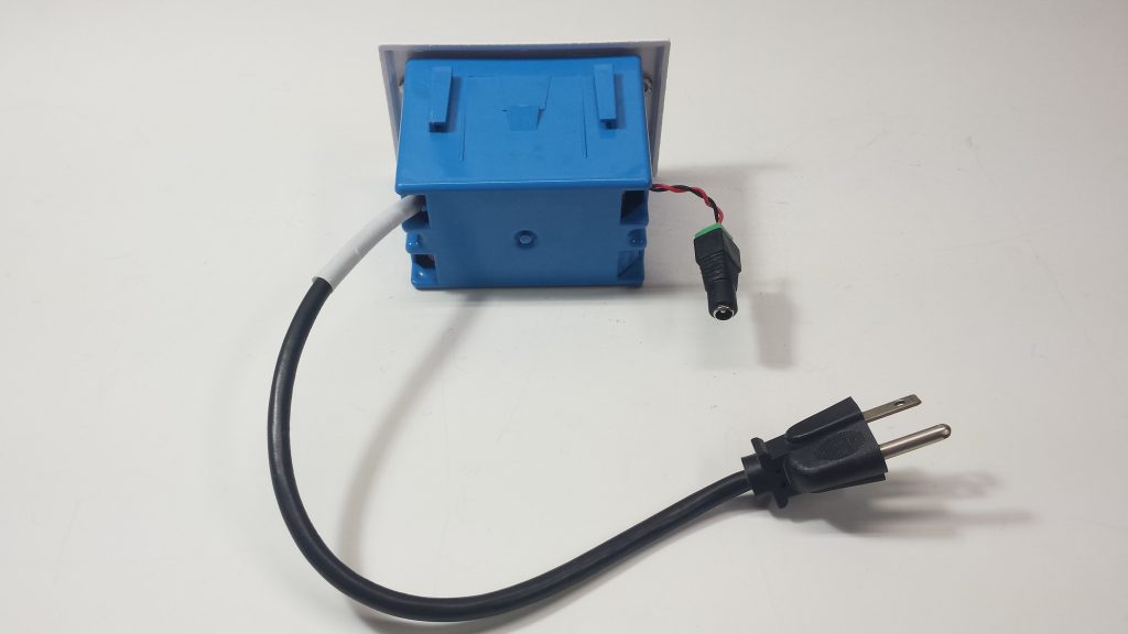
IoT enabled electrical outlet
Enabling an electrical outlet to connect to a Wi-Fi is not difficult. I used an ESP8266 wi-fi microcontroller to control a relay that switches the mains power on and off. I used an Adafruit Huzzah board which is just a convenient breakout board for the ESP8266. The relay control wire is connected to an ESP8266 GPIO pin and a simple Arduino program running on the ESP8266 makes it easy to control the relay. There are several ways to program an ESP8266, but I prefer to use Arduino. See this guide for instructions on how to get started programming the ESP8266 with the Arduino IDE.
Here is the schematic for the circuit. I power the circuit with a common 9V adapter. A voltage regulator provides 5V to the relay coil and to the Huzzah board (which has an onboard 3.3V regulator to power the ESP8266). Note that the GPIO pins are 3.3V, but I found no problems controlling the 5V relay with 3.3V logic.
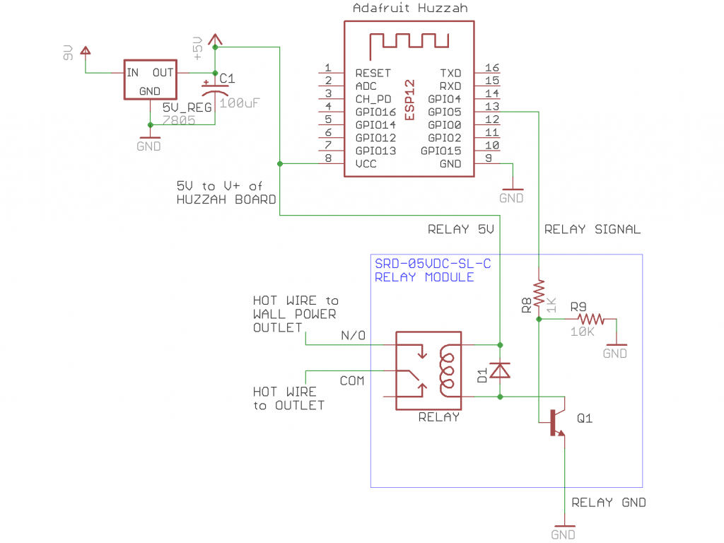
An ordinary wall plug connects this IoT outlet box to normal outlet in the wall, and the wires are connected to the outlet enclosed in the box. The relay connects and disconnects the “line” or “hot” wire of the mains circuit. That is, the relay is between the wall power and the outlet provided by this outlet box. Here’s how it looks all closed up.
Controlling the Outlet from the Internet with MQTT
Now that we have a way for Arduino code to turn the power on and off, how do we connect it to the Internet and control it? Step one is to get connected to your Wi-Fi network. This is very easy, and to keep things simple, the source code for this project just has you hard code your SSID and password. But we still need a way to send a command to the outlet. I’m using MQTT for this purpose, which is implemented by the Arduino PubSubClient library. MQTT allows the outlet to subscribe to an MQTT topic on an MQTT broker. An MQTT broker allows different MQTT clients to publish messages to topics and/or subscribe to topics. I run my own MQTT broker for all my MQTT projects, but you can set up a free account on CloudMQTT. Their free plan allows you to have up to 10 connections. The source code for this project makes it clear where to set the information for your account: username, password, server, and port. This project uses an SSL connection, so use the SSL port on your CloudMQTT server.
The outlet subscribes to a topic called “coffee-maker” and my phone will publish messages to that topic. If the outlet receives a message “ON” on this topic, it will turn the relay on. If it receives an “OFF” message, the relay is switched off. You can also specify a delay so that the outlet is switched off after a period of time. My coffee will be done brewing within 10 minutes, so I want everything switched off. To do this, I send the message “ON”, but also with the number of seconds for the auto-off delay. For 10 minutes, I send “ON:600”.
Remote Control on the Phone
I have an Android phone and use a simple app called MQTT Dash. It lets you create dashboards with controls on them. My coffee maker dashboard has a button that can toggle between on and off for the outlet. It’s green when the outlet is turned on and publishes the message “ON:600” to the topic coffee-maker, and is red when I publish “OFF” to to the same topic. Here is the setup for the control:
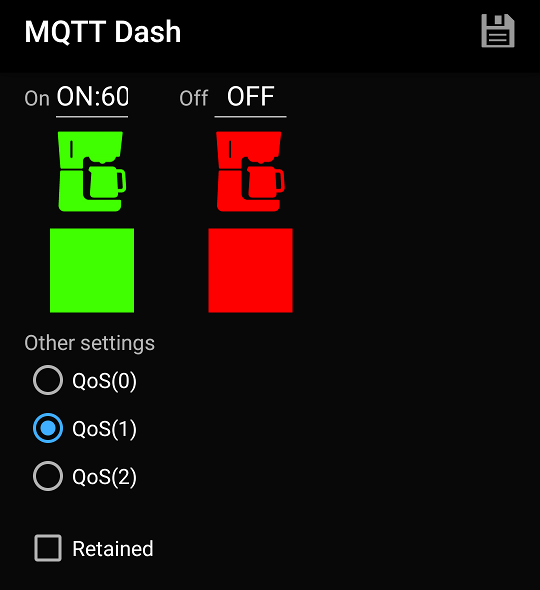
MQTT Dash has many icons to choose from when creating a button — even a coffee maker icon! This gives me a great little dashboard for my coffee maker. Just tap to turn it on/off!

Project source code at GitHub: iot-wifi-outlet
Individually Addressable Incandescent Lamps
Everyone playing with electronics these days knows about LED strips made of dozens or hundreds of individually addressable RGB LEDs. I love them and make great use of them in the nootropic design Lumazoid music visualizer. But what about incandescent lamps? Old-school light bulbs with a filament have a soft warm glow that you just can’t get from LEDs. Wouldn’t it be great to be able to control a bunch of lamps individually by setting their brightness in code on a microcontroller? This is just what I set out to do recently, and the results are great.

Individually addressable lamp module
How it works
I simply used the same technology as LED strips to allow communication between lamp modules. LED strips have RGB LEDs with an embedded driver chip which uses PWM (pulse width modulation) to control the duty cycle on the red, green, and blue LEDs. This combined LED/chip is called WS2812 or WS2812B. On older LED strips, the driver chip was not embedded into the LED itself, but was a separate chip called WS2811. These standalone driver chips are somewhat obsolete now which means they are cheap! I got 50 of them on eBay for $5.00. Since these modules use the same technology as LED strips, the same code can be used. Adafruit’s NeoPixel library is a very simple way to control LEDs, so we can control each lamp easily. The lamp is controlled by the “blue” pin on the WS2811 so that is the value to set.
lamps.setPixelColor(lampNum, pixels.Color(0, 0, brightness));
Circuit
The driver chip cannot sink enough current to control a lamp directly, so I connected one of the LED output pins (the pin designated for blue) to a P-channel MOSFET. The PWM output from the WS2811 pin controls the MOSFET gate and the MOSFET then controls the current flowing to the lamp. I tried several MOSFETs to find one that worked best for a 5V source and allowed good control at very low PWM duty cycle. The FQP27P06 MOSFET allows the lamp filament to glow at an almost imperceptible level at a PWM duty cycle of 1/255. Since a lamp filament takes a bit of time to turn on/off, there is no flicker at low duty cycles. Nice!

Notice that the module has a big 1500uF capacitor. This is because the PWM creates a lot of ripple in the power line that needs to be smoothed out. At first I did not experience this when using only one WS2811/MOSFET/lamp in the circuit, but as soon as I added more there was lots of flickering caused by power line noise. A big fat cap solved that.
Lamp bulbs and sockets
The board is designed to allow the lamp socket to be mounted on the top or the bottom. That’s why there are 2 lamps in the schematic. There are also solder pads with holes to allow wires to be attached if I don’t want the lamp directly on the board. I used E10 miniature sockets from eBay and #27 bulbs with an E10 miniature base. These are 5V bulbs that draw up to 300mA. These can be bought at Mouser (part number 560-27). Or you can get them and lots of other bulbs from Bulb Town. Who knows more about bulbs than Bulb Town? Nobody, that’s who.
Power
If you are using lots of them at full brightness, you’ll need a beefy power supply. I have 20 lamp modules strung together and power it with a 10A supply. If I try to set all 20 lamps to full brightness at the same time, the lamps at the end of the string are dim because of the resistance in the power wires, so my Arduino driver programs need to account for this. Also, a lamp filament doesn’t turn on/off immediately like an LED, so I also had to take this in consideration in my programs. This slowness in the on/off actually smooths out the illumination so there is no flicker, even at very low duty cycles.
Conclusion
I’m really happy with how this all turned out. I’m not planning on offering these modules as a product because I think the minimum price would need to be about $7 each, which I’m not sure people would want to pay. If you really think I should offer these or are interested, please let me know.
The Eagle files and gerber files are available here.
Frequency Filtering with the Audio Hacker Shield
The Audio Hacker shield for Arduino lets you do some cool things with digital signal processing. This new project shows how a fairly simple Arduino sketch can implement a low-pass filter, high-pass filter and band-pass filter.
A low-pass filter allows low frequencies to pass through (makes sense, right?) while attenuating or cutting out the frequencies that are higher than a specified cutoff frequency.
A high-pass filter is the opposite. It lets high frequencies through while attenuating frequencies below the cutoff frequency.
A band-pass filter lets frequencies that are near the cutoff frequency to pass through but attenuates the frequencies above and below it.
There is a new example sketch included in the Audio Hacker library called “Filter” that implements these 3 filters. In the video below I’m using the DJ Shield to make it easy to provide inputs but it is not strictly required. An audio source is plugged into the Audio Hacker input. A pot connected to A0 controls the cutoff frequency. A button on digital pin 5 starts/stops the audio processing, and a button on digital pin 4 controls the filter selection. I’m lighting up the red LED for low-pass filter, blue LED for high-pass filter, and both LEDs for band-pass filter.
Now shown in the video is the effect of the filter resonance. The pot conntected to A1 controls the resonance of the filter. Resonance amplifies the frequencies around the cutoff frequency, and has an especially cool effect when using a low-pass filter.
The resonant filter implemented here is adapted from the code here. I hope this simple project lets you hear how different filters sound and gives you something new to explore with your Audio Hacker shield!
Using a Video Experimenter as MIDI Controller
This simple project shows how a video signal captured by a Video Experimenter Shield can be used to send MIDI messages to a synthesizer. A small camera module is connected to the input of the Video Experimenter (the red wire in the picture is for powering the camera from the Arduino VIN pin). The video output goes to a small TV. A MIDI shield sits atop the Video Experimenter to allow the Arduino to send MIDI messages to a Synthino XM synthesizer. By the way, the Synthino XM is our new synthesizer product and you can read all about it on synthino.com. It’s awesome.
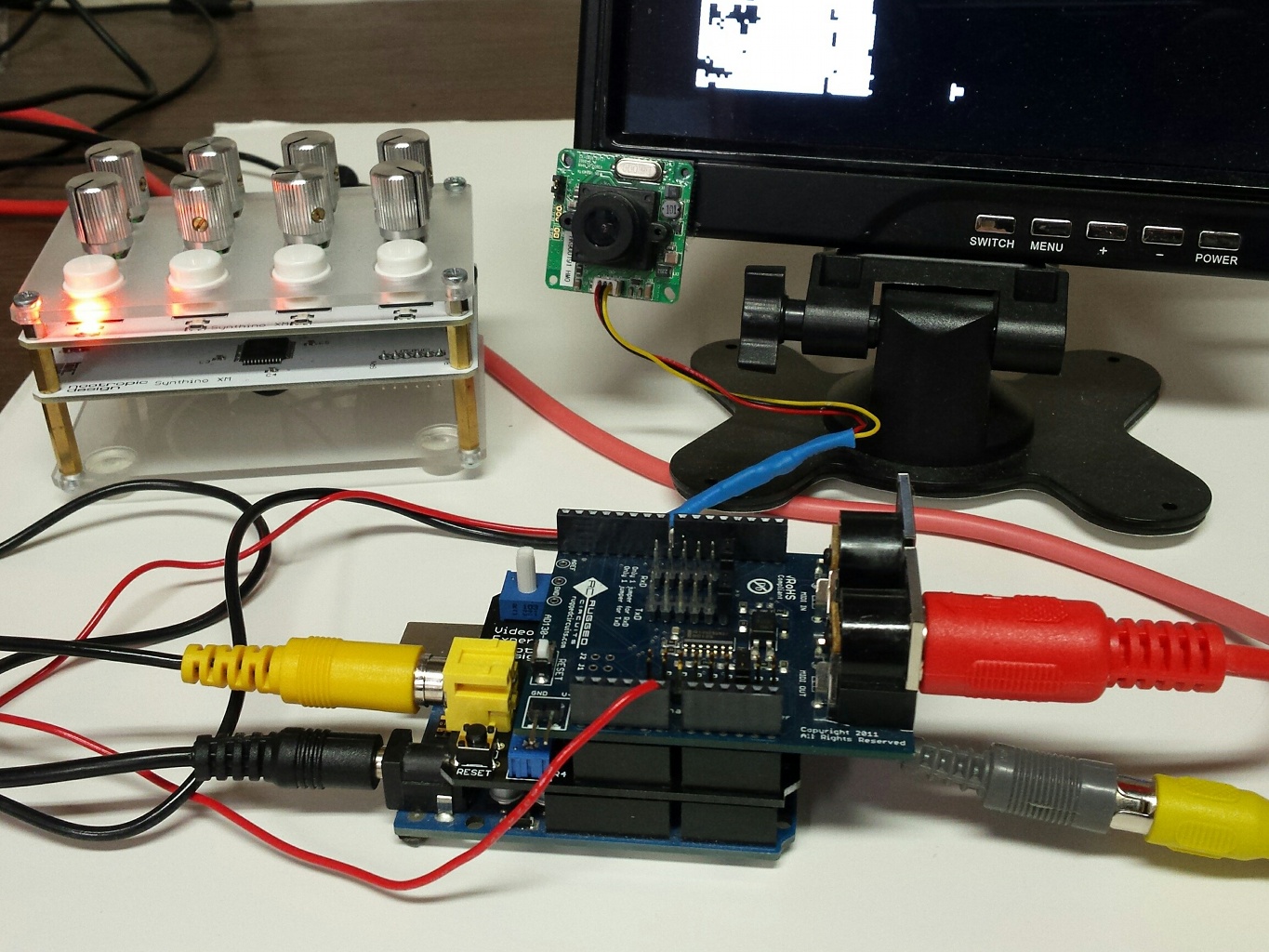
The Arduino sketch uses the Video Experimenter’s frame capture ability to capture simple monochrome low-res frames. The “on” pixels are counted to determine the pitch of the note that should be sent to the synthesizer. The code then just sends a MIDI note-on message to play a note on the synth. The brigher the image (more “on” pixels) sends higher pitched notes. In the video you can see me adjusting the Video Experimenter threshold knob to alter the brightness and also shining a flashlight on the camera.
This source code for this project is the example “VideoMIDI” in the TVout library for Video Experimenter.
