Difficulty Level = 5 [What’s this?]
UPDATE: I have re-done this project using simple 434MHz RF transmitter/receiver devices. Check out the new project!.
UPDATE: Also see this project for an easy way to display a temperature reading: Digit Shield Temperature Display.
I decided to explore the more advanced features of XBee radios by building a remote temperature sensor. You can get quite a bit of control over an XBee radio without a microcontroller at all. You can configure the radio to send sensor readings at particular intervals when it detects changes on certain input pins. For the details on configuring XBee radios, see the documentation at Digi International.
For this project, I configured the radio at the sensor end to read the analog input of pin 19 every 4 seconds and to send a sensor reading packet. Both the sender and receiver radios must be running the API firmware. This does not work if they are running the default AT firmware. And the “API” parameter is not the same as running the API firmware. You literally need to write a different firmware image to your radios using the X-CTU tool from Digi. I have Series 2 radios, so if you are using Series 1, you need to read the correct documentation for your radios and modify the code.
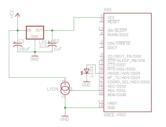
Input pin 19 on my sensor radio is configured (parameter D1) with value ‘2’ which means that it will read analog input, and the IO sampling rate (parameter IR) is set to ‘1000’ which sends a sample every 4096ms.
An LM34 temperature sensor outputs a variable voltage depending on the temperature. The mapping is extremely simple: 10mV for every Fahrenheit degree. So, at 72 degrees F, the output is 720mV.
Why did I choose pin 19? I started with pin 20, but I burned it out. The pins can only handle an analog input of up to 1.2V, and I think I may have sent too much into the pin. How? Well, let’s say it involved holding a cold Pepsi can on the circuit to cool off the temperature sensor, and I shorted out a connection with the can. Oops. I’m lucky I didn’t burn out the entire XBee chip.

Remote temperature sensor

Schematic for remote sensor circuit

Arduino with XBee shield and LED display
#define NUM_DIGITAL_SAMPLES 12
#define NUM_ANALOG_SAMPLES 4

int groundPins[7] = {8, 2, 3, 4, 5, 9, 7};
int digitPins[2] = {11, 10};
int ON = HIGH;
int OFF = LOW;
int number[10][7];
int digit[2];
int TOP = 0;
int UPPER_L = 1;
int LOWER_L = 2;
int BOTTOM = 3;
int LOWER_R = 4;
int UPPER_R = 5;
int MIDDLE = 6;

int index;
int n = 0;

int packet[32];
int digitalSamples[NUM_DIGITAL_SAMPLES];
int analogSamples[NUM_ANALOG_SAMPLES];

void setup()
{
  Serial.begin(9600);

  for(int i=0;i<7;i++) {
    pinMode(groundPins[i], OUTPUT);
  }
  for(int i=0;i<2;i++) {
    pinMode(digitPins[i], OUTPUT);
  }
  initNumber();

  setDigit(n);
}

void loop() {
  readPacket();
  drawDisplay();
}

void readPacket() {
  if (Serial.available() > 0) {
    int b = Serial.read();
    if (b == 0x7E) {
      packet[0] = b;
      packet[1] = readByte();
      packet[2] = readByte();
      int dataLength = (packet[1] << 8) | packet[2];

      for(int i=1;i<=dataLength;i++) {
        packet[2+i] = readByte();
      }
      int apiID = packet[3];
      packet[3+dataLength] = readByte(); // checksum

      printPacket(dataLength+4);

      if (apiID == 0x92) {
        int analogSampleIndex = 19;
        int digitalChannelMask = (packet[16] << 8) | packet[17];
        if (digitalChannelMask > 0) {
          int d = (packet[19] << 8) | packet[20];
          for(int i=0;i < NUM_DIGITAL_SAMPLES;i++) {
            digitalSamples[i] = ((d >> i) & 1);
          }
          analogSampleIndex = 21;
        }

        int analogChannelMask = packet[18];
        for(int i=0;i<4;i++) {
          if ((analogChannelMask >> i) & 1) {
            analogSamples[i] = (packet[analogSampleIndex] << 8) | packet[analogSampleIndex+1];
            analogSampleIndex += 2;
          } else {
            analogSamples[i] = -1;
          }
        }
      }
    }

    int reading = analogSamples[1];  // pin 19
    // convert reading to millivolts
    float v = ((float)reading/(float)0x3FF)*1200.0;

    // convert to Fahrenheit.  10mv per Fahrenheit degree
    float f = v / 10.0;

    // round to nearest int
    n = (int)(f+0.5);
    setDigit(n);
  }
}

void drawDisplay() {
  for(int g=0;g<7;g++) {
    digitalWrite(groundPins[g], LOW);
    for(int i=0;i<2;i++) {
      if (digit[i] < 0) {
        continue;
      }
      digitalWrite(digitPins[i], number[digit[i]][g]);
    }
    delay(0);  // for some reason, this is required even if the value is 0
    digitalWrite(groundPins[g], HIGH);
  }
}

void setDigit(int n) {
  n = n % 100;
  digit[0] = n % 10;
  digit[1] = (n / 10) % 10;
  if ((digit[1] == 0) && (n < 10)) {
    digit[1] = -1;
  }
}

void initNumber() {
  number[0][0] = ON;
  number[0][1] = ON;
  number[0][2] = ON;
  number[0][3] = ON;
  number[0][4] = ON;
  number[0][5] = ON;
  number[0][6] = OFF;

  number[1][0] = OFF;
  number[1][1] = OFF;
  number[1][2] = OFF;
  number[1][3] = OFF;
  number[1][4] = ON;
  number[1][5] = ON;
  number[1][6] = OFF;

  number[2][0] = ON;
  number[2][1] = OFF;
  number[2][2] = ON;
  number[2][3] = ON;
  number[2][4] = OFF;
  number[2][5] = ON;
  number[2][6] = ON;

  number[3][0] = ON;
  number[3][1] = OFF;
  number[3][2] = OFF;
  number[3][3] = ON;
  number[3][4] = ON;
  number[3][5] = ON;
  number[3][6] = ON;

  number[4][0] = OFF;
  number[4][1] = ON;
  number[4][2] = OFF;
  number[4][3] = OFF;
  number[4][4] = ON;
  number[4][5] = ON;
  number[4][6] = ON;

  number[5][0] = ON;
  number[5][1] = ON;
  number[5][2] = OFF;
  number[5][3] = ON;
  number[5][4] = ON;
  number[5][5] = OFF;
  number[5][6] = ON;

  number[6][0] = ON;
  number[6][1] = ON;
  number[6][2] = ON;
  number[6][3] = ON;
  number[6][4] = ON;
  number[6][5] = OFF;
  number[6][6] = ON;

  number[7][0] = ON;
  number[7][1] = OFF;
  number[7][2] = OFF;
  number[7][3] = OFF;
  number[7][4] = ON;
  number[7][5] = ON;
  number[7][6] = OFF;

  number[8][0] = ON;
  number[8][1] = ON;
  number[8][2] = ON;
  number[8][3] = ON;
  number[8][4] = ON;
  number[8][5] = ON;
  number[8][6] = ON;

  number[9][0] = ON;
  number[9][1] = ON;
  number[9][2] = OFF;
  number[9][3] = ON;
  number[9][4] = ON;
  number[9][5] = ON;
  number[9][6] = ON;
}
void printPacket(int l) {
  for(int i=0;i < l;i++) {
    if (packet[i] < 0xF) {
      // print leading zero for single digit values
      Serial.print(0);
    }
    Serial.print(packet[i], HEX);
    Serial.print(" ");
  }
  Serial.println("");
}

int readByte() {
    while (true) {
      if (Serial.available() > 0) {
      return Serial.read();
    }
  }
}
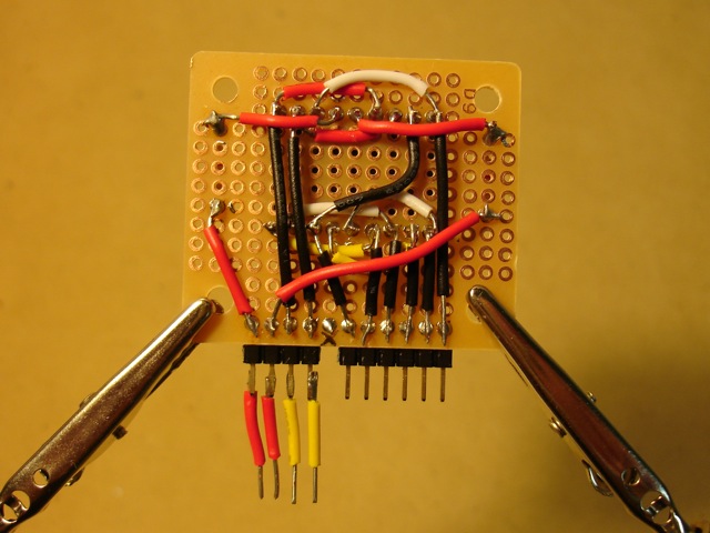
Here’s how I wired the back of the LED display. The code displays each digit separately to save Arduino pins but toggles between the digits so fast you can’t see any flicker.

Back of LED display. The pin positions are designed to fit the XBee shield.

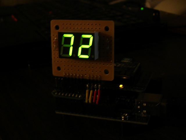
In the dark!

do u have helpful ideas for this subject?
This project shows how to transmit sensor readings. Code and schematics are provided! That may help you get started with your project.
hi ,can implement this project without Arduino
thanks
Michael, you have the patience of a saint. Tell these blood suckers to do their own research.
Wonderful info you provided here, thanks for sharing.
Good Work!
Ravi Saini
http://www.nrdcentre.com
unable to connect xbee with arduino..please help me to figure it out
Professional!
So it seems that you are really lucky not to burn out the entire XBee chip.