Difficulty Level = 5 [What’s this?]
UPDATE: I have re-done this project using simple 434MHz RF transmitter/receiver devices. Check out the new project!.
UPDATE: Also see this project for an easy way to display a temperature reading: Digit Shield Temperature Display.
I decided to explore the more advanced features of XBee radios by building a remote temperature sensor. You can get quite a bit of control over an XBee radio without a microcontroller at all. You can configure the radio to send sensor readings at particular intervals when it detects changes on certain input pins. For the details on configuring XBee radios, see the documentation at Digi International.
For this project, I configured the radio at the sensor end to read the analog input of pin 19 every 4 seconds and to send a sensor reading packet. Both the sender and receiver radios must be running the API firmware. This does not work if they are running the default AT firmware. And the “API” parameter is not the same as running the API firmware. You literally need to write a different firmware image to your radios using the X-CTU tool from Digi. I have Series 2 radios, so if you are using Series 1, you need to read the correct documentation for your radios and modify the code.
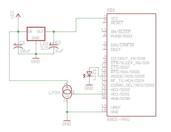
Input pin 19 on my sensor radio is configured (parameter D1) with value ‘2’ which means that it will read analog input, and the IO sampling rate (parameter IR) is set to ‘1000’ which sends a sample every 4096ms.
An LM34 temperature sensor outputs a variable voltage depending on the temperature. The mapping is extremely simple: 10mV for every Fahrenheit degree. So, at 72 degrees F, the output is 720mV.
Why did I choose pin 19? I started with pin 20, but I burned it out. The pins can only handle an analog input of up to 1.2V, and I think I may have sent too much into the pin. How? Well, let’s say it involved holding a cold Pepsi can on the circuit to cool off the temperature sensor, and I shorted out a connection with the can. Oops. I’m lucky I didn’t burn out the entire XBee chip.

Remote temperature sensor

Schematic for remote sensor circuit

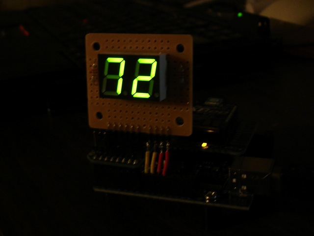
Arduino with XBee shield and LED display
#define NUM_DIGITAL_SAMPLES 12
#define NUM_ANALOG_SAMPLES 4

int groundPins[7] = {8, 2, 3, 4, 5, 9, 7};
int digitPins[2] = {11, 10};
int ON = HIGH;
int OFF = LOW;
int number[10][7];
int digit[2];
int TOP = 0;
int UPPER_L = 1;
int LOWER_L = 2;
int BOTTOM = 3;
int LOWER_R = 4;
int UPPER_R = 5;
int MIDDLE = 6;

int index;
int n = 0;

int packet[32];
int digitalSamples[NUM_DIGITAL_SAMPLES];
int analogSamples[NUM_ANALOG_SAMPLES];

void setup()
{
  Serial.begin(9600);

  for(int i=0;i<7;i++) {
    pinMode(groundPins[i], OUTPUT);
  }
  for(int i=0;i<2;i++) {
    pinMode(digitPins[i], OUTPUT);
  }
  initNumber();

  setDigit(n);
}

void loop() {
  readPacket();
  drawDisplay();
}

void readPacket() {
  if (Serial.available() > 0) {
    int b = Serial.read();
    if (b == 0x7E) {
      packet[0] = b;
      packet[1] = readByte();
      packet[2] = readByte();
      int dataLength = (packet[1] << 8) | packet[2];

      for(int i=1;i<=dataLength;i++) {
        packet[2+i] = readByte();
      }
      int apiID = packet[3];
      packet[3+dataLength] = readByte(); // checksum

      printPacket(dataLength+4);

      if (apiID == 0x92) {
        int analogSampleIndex = 19;
        int digitalChannelMask = (packet[16] << 8) | packet[17];
        if (digitalChannelMask > 0) {
          int d = (packet[19] << 8) | packet[20];
          for(int i=0;i < NUM_DIGITAL_SAMPLES;i++) {
            digitalSamples[i] = ((d >> i) & 1);
          }
          analogSampleIndex = 21;
        }

        int analogChannelMask = packet[18];
        for(int i=0;i<4;i++) {
          if ((analogChannelMask >> i) & 1) {
            analogSamples[i] = (packet[analogSampleIndex] << 8) | packet[analogSampleIndex+1];
            analogSampleIndex += 2;
          } else {
            analogSamples[i] = -1;
          }
        }
      }
    }

    int reading = analogSamples[1];  // pin 19
    // convert reading to millivolts
    float v = ((float)reading/(float)0x3FF)*1200.0;

    // convert to Fahrenheit.  10mv per Fahrenheit degree
    float f = v / 10.0;

    // round to nearest int
    n = (int)(f+0.5);
    setDigit(n);
  }
}

void drawDisplay() {
  for(int g=0;g<7;g++) {
    digitalWrite(groundPins[g], LOW);
    for(int i=0;i<2;i++) {
      if (digit[i] < 0) {
        continue;
      }
      digitalWrite(digitPins[i], number[digit[i]][g]);
    }
    delay(0);  // for some reason, this is required even if the value is 0
    digitalWrite(groundPins[g], HIGH);
  }
}

void setDigit(int n) {
  n = n % 100;
  digit[0] = n % 10;
  digit[1] = (n / 10) % 10;
  if ((digit[1] == 0) && (n < 10)) {
    digit[1] = -1;
  }
}

void initNumber() {
  number[0][0] = ON;
  number[0][1] = ON;
  number[0][2] = ON;
  number[0][3] = ON;
  number[0][4] = ON;
  number[0][5] = ON;
  number[0][6] = OFF;

  number[1][0] = OFF;
  number[1][1] = OFF;
  number[1][2] = OFF;
  number[1][3] = OFF;
  number[1][4] = ON;
  number[1][5] = ON;
  number[1][6] = OFF;

  number[2][0] = ON;
  number[2][1] = OFF;
  number[2][2] = ON;
  number[2][3] = ON;
  number[2][4] = OFF;
  number[2][5] = ON;
  number[2][6] = ON;

  number[3][0] = ON;
  number[3][1] = OFF;
  number[3][2] = OFF;
  number[3][3] = ON;
  number[3][4] = ON;
  number[3][5] = ON;
  number[3][6] = ON;

  number[4][0] = OFF;
  number[4][1] = ON;
  number[4][2] = OFF;
  number[4][3] = OFF;
  number[4][4] = ON;
  number[4][5] = ON;
  number[4][6] = ON;

  number[5][0] = ON;
  number[5][1] = ON;
  number[5][2] = OFF;
  number[5][3] = ON;
  number[5][4] = ON;
  number[5][5] = OFF;
  number[5][6] = ON;

  number[6][0] = ON;
  number[6][1] = ON;
  number[6][2] = ON;
  number[6][3] = ON;
  number[6][4] = ON;
  number[6][5] = OFF;
  number[6][6] = ON;

  number[7][0] = ON;
  number[7][1] = OFF;
  number[7][2] = OFF;
  number[7][3] = OFF;
  number[7][4] = ON;
  number[7][5] = ON;
  number[7][6] = OFF;

  number[8][0] = ON;
  number[8][1] = ON;
  number[8][2] = ON;
  number[8][3] = ON;
  number[8][4] = ON;
  number[8][5] = ON;
  number[8][6] = ON;

  number[9][0] = ON;
  number[9][1] = ON;
  number[9][2] = OFF;
  number[9][3] = ON;
  number[9][4] = ON;
  number[9][5] = ON;
  number[9][6] = ON;
}
void printPacket(int l) {
  for(int i=0;i < l;i++) {
    if (packet[i] < 0xF) {
      // print leading zero for single digit values
      Serial.print(0);
    }
    Serial.print(packet[i], HEX);
    Serial.print(" ");
  }
  Serial.println("");
}

int readByte() {
    while (true) {
      if (Serial.available() > 0) {
      return Serial.read();
    }
  }
}
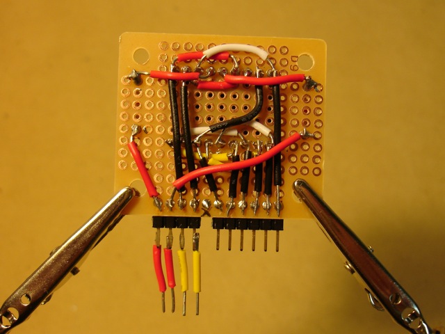
Here’s how I wired the back of the LED display. The code displays each digit separately to save Arduino pins but toggles between the digits so fast you can’t see any flicker.

Back of LED display. The pin positions are designed to fit the XBee shield.

In the dark!

Thats nice! I need to get a Xbee sometime :P
Tytower did one with the cheaper modules but an arduino under the transmitter which allows for multiple sensors including digital. All up cheaper than an XBee and a range of 3 miles.
http://www.arduino.cc/cgi-bin/yabb2/YaBB.pl?num=1256188633
@arnoldF: I read that thread, where did you read he is getting 3 miles range?
I PM’d hm and that was his estimate .I’m building one now hence my interest in yours. I’ve tested the transmitter to about 600meters atm.What distance in the clear does yours cover thanks?
I have the XBee Pro radios with published range of up to 1 mile. I only did a range test once and got about 1/4 mile (outdoors). In practice, the range is much less than published, especially if you do not have a directional antenna.. I even talked to an engineer at Digi about it.
Hey-
Awesome post, being able to use the Xbee with a standalone sensor is great. Looking at the schematic, it seems like pins 1 & 2 of the LM34 are both connected to ground. Is this accurate or is the lM34 actually connected to Vcc?
Eric,
OMG, you are right — definitely an error in my schematic. The LM34 won’t work too well with pins 1&2 connected to GND, eh?
Eric,
Schematic updated to reflect reality and sound electrical concepts.
I understand that this is for learning about the XBee but if someone reading this wants to simply have remote wireless sensors around their house they should look at a JeeNode which is based on a ATmega328 and wireless and much cheaper.
I’m new to Xbee and Arduino, I’ve build a couple tutorial projects so far. I want to try this project and I have a couple of questions:
How should the Xbees be configured?
What is the power supply voltage on the transmitter board?
I see that pin 1 on the LM34 is connected to the positive side of the power supply. If the p/s voltage varies will it impact the temperature reading?
–Scott
Scott216:
Configure the XBee radios to communicate with one another (set the addresses correctly) and use the API firmware. One radio will need to be running the coordinator firmware. The only other thing to do is set one of the analog pins to sample analog values. I set parameter D1 to value ‘2’. And I set parameter IR to ‘1000’ to set the sampling rate to once every 4096ms. That’s the only config needed. The source voltage for the transmitter is 5V. The LM34 requires 5V. The 3.3V voltage regulator steps the voltage down for the XBee which requires 3.3V. I don’t know the answer to your last question about variation in VCC. I suppose if it varies it could affect the analog output of the LM34. So you should use a regulated power source for VCC. Perhaps add a 5V voltage regulator to your transmitter.
I’m trying to get this working. I took your code and removed the parts that drive the LCD display. You can see it here: http://www.arduino.cc/cgi-bin/yabb2/YaBB.pl?num=1264655063
I hooked up a temp sensor to pin 19, just like you did. I think the Xbees are configured correctly, but I wasn’t sure about what API mode I should be using. I don’t think I changed it, so it’s probably the default AP=0.
The packets that I’m getting look like:
7E 00 0A 83 00 01 20 00 01 04 00 03 FF 54
7E 00 0A 83 00 01 1F 00 01 04 00 03 FF 55
I went to the Xbee product manual (pg 58-63) to try and decipher these. I’m stuck on the 4th byte which is 83 for me. I think this is the API Identifier, but I don’t see 0x83 listed in the Xbee manual.
I’m using Series 1 Xbee. The voltage going into pin 19 on the transmitter is about 1.8 volts. When I do a Serial.println(reading); I get zero.
–Scott
Michael could you please explain API configuration step by step . It is hampering my project which is very similar to what you have done here .
Hi, i’m new in Xbee fields .
I wonder if in the receiving side , i use a xbee connect to the PC , how can we receive the data in clear form , such as “72 degrees F” ?
Cause in X-CTU , i think we just receive data as a packet with HEX numbers
Can you help me? Please!
If you are using the normal “transparent” mode (that is, not API mode), then it’s just like a normal serial connection. You can send strings just as you normally would over a serial connection. Just read the XBee documentation.
THANKS Michael! I have been learning volumes reading your code. You referred me here from the Adafruit formus.
Hi nootropic design,
The pin assignments on your circuit drawing indicates that you used a XBee 802.15.4 module. I recently purchased 8 XBee ZB modules, and I am aware of the differences in pin assignments between these modules and the 802.15.4 ones. What deviations from your project would I need to make in order to build wireless temperature sensors out of the ZB modules?
Best regards,
L
ljeung: I am not familiar with the modules that you own, so I can’t tell you how to wire them. Have you studied the datasheet for the modules you own?
Hi Michael,
Yes, I’ve studied the datasheet and also the manual for my modules. In particular, I’ve studied their pin assignments (on page 13 of the ZB module’s manual at http://ftp1.digi.com/support/documentation/90000976_F.pdf) and compared them to the ones on 802.15.4 modules (see page 7 of 802.15.4 module’s manual at http://ftp1.digi.com/support/documentation/90000982_B.pdf.)
L
ljeung: ok, I think you will find that you don’t have to make any changes, right? The pin assignments are the same for the pins used in the project. VCC, GND, and analog input 1.
Okay, thanks, Michael.
L
I’m trying the same experiment with my XBee and an LM19 Temp sensor. When i recieve the result at the local XBee (Coordinator), the Remote one attached to the sensor (End device) always sends me the value 1024. I’ve measured the mV in the sensor output and it is around 800mV (below 1.1V). How do you decrease the output voltage? is it with those capacitors C1, C2??
@olmo:
Hmm. I’m not sure what is going wrong for you. The capacitors are for power conditioning. A voltage of 800mV should result in a reading of about 682 (hex 0x2AB). Sounds like you are getting a value of 0x3FF in your packet? Take a closer look at the packet parsing and the raw packet. I was using pin 19 on the XBee. Are you also using pin 19?
Exactly. The result i get is 03 FF, but it’s quite random tho. My sensor has around 690 mV on its output and the results i get are sometimes stable 1024, sometimes unstable random numbers. example (real measures): 0, 1023, 0, 624, 1023, 0, 17, 1023, 526 …
The measures are taken in the pin named D1/ADC1, with D1=2, which means analog.
How do you attach the sensor output to the D1 pin? solder it maybe? i’m afraid the contact beetween metals is not good enough, or maybe my XBIB-R-DEV board is not working properly :( the mV coming from the sensor are stable and ok, but the results are random. I parse the frames with the Xbee-api java library, so i don’t think that’s the problem. I’ve also tried monitoring em via X-CTU.
@olmo:
I have used a breadboard to connect the sensor to the XBee. Maybe you have a bad connection?
Probably the link beetween the sensor output and the XBee pin is not good enough. I have to try to put it into a breadboard. How do you feed the XBee outside the Dev.Board? which pins do you have to feed with 12V and which to GND? do you have a quick guide or schematic? Thank you very much
@olmo:
I’m not sure what you mean by “Dev.Board”. I just put an XBee on a breadboard as shown above. The schematic is above.
Hello,
I’m new with Xbee and i’m trying to understand your code, but i dont know what apiID = 0x92 is. I have been searching the manual but i dont found this configuration. Could u explain it please? (sorry if my question is very simple but I am lost with this) Thanks
API id 0x92 is the identifier for an I/O Data Sample. See page 67 of http://ftp1.digi.com/support/documentation/90000866_C.pdf for the API frame layout of the I/O sample.
I have a senior design project for the University similar to this and was wondering if you can take multiple remote temp sensors and send this back to the Arduino receiver?Possibly showing the different values through the web.
Yes, XBee radios are designed to form mesh networks. So you can have multiple end devices sending information to the coordinator.
can i have u’r schismatic diagram for the led display .
can i know the arduino code is testing the led light or sensing the temperature?
@jason: I would not worry about how I wired the LED display. I should have had a resistor on each LED, but took a shortcut. Just search the internet for the many resources on 7 segment displays.
@billy: I do not understand your question. What do you mean?
I was wondering how I could modify this code to simply display the temperature in the serial monitor… I’m having a slight difficulty determining what modules are for receiving information and which are for the LED display… Thanks so much :-D
@EngGirl
Instead of calling drawDisplay(), just call Serial.println(n);
Thanks so much… unfortunately I can’t quite say that I have my temperature sensor up and working yet because I just turned the power on to only receive values of 0 and for my temperature sensor to get so hot it burnt my finger… so needless to say I’ll keep trying but thank you for your speedy response!
If the sensor gets hot, then you don’t have the power connected correctly…! Look at the datasheet carefully for the pinout.
Thanks so much… I fixed the configuration of the temperature sensor and now I am getting data… however, not quite the data that I expected. I’m getting hex values every four seconds (the four seconds was expected). What I originally thought was that the last two digits of the hex output was the temperature but when I converted it to decimal it gave me numbers like 50 degrees which was entirely colder than it was in the room. I then tested it with a blow dryer and it didn’t change. I’m thinking that it’s possible that the temperature sensor no longer works after being fried. Thanks so much for all of your help though as well as your speedy responses!
my 7 segment light up d.but cant recieve the temperature.isit the code have problem? About the X-CTU, after i send the code into the board my X-CTU can communicate with the board dy…and solution to fix that?
EngGirl you can run the whole thing? can i have your contact? email? or msn? because i really urgent to have ur information to run my project..thank.
Hi – cool project. I am trying to replicate this to learn a bit more about XBees and API coding. I have two XBees configured with the ZigBee API firmware, one as a co-ordinator, the other as a Router/End Device. I can see nowhere to set the IR value in the XBee config via X-CTU. Can you help ?? Cheers.
@ilium007 – In the X-CTU tool, read in the values from the modem. Then under IO Settings, there is another group of parameters called IO Sampling. Expand that set and you’ll see the IO Sampling Rate parameter (IR).
I am obviously doing something wrong !!!
http://dl.dropbox.com/u/973862/forums/Digi_X-CTU_IO.png
Would someone be able to take a look at the X-CT screenshot above and see if you can see what I am doing wrong ? There is no IO Sampling attributes there for me to change !
Hi…is that any different i change lm 34 to lm 35? Does Xbee at the remote temerature sensor part by adding any PIC to run it? or it can run without PIC? im a newbee on this arduino and xbee project.
@ilium007: There is an IO Sampling section in my modem configuration when I use X-CTU. My devices are XBee Pro so the device is XBP24-B and my firmware is ZNET 2.5 ROUTER/END DEVICE. Looks like your devices are not XBee Pro, so they are different. I don’t know if you can set the IO sampling rate for your devices — what does your datasheet say about it? You did read the datasheet I assume.
@billy: Compare the datasheet for the LM35 to the LM34. It looks like the pinout is the same, so you should be able to use the LM35 centigrade sensor, but you’ll obviously need to change the temperature calculations. No, there is not a PIC microcontroller running the XBee. The schematic is included in the project.
@Michael – the manual I have for the XBee (XB24-B) does state the IR setting, but given I could not find it in the GUI I used the Python API to remotely set it. I gace up late Sat night and played GT5 on PS3 instead.