Difficulty Level = 6 [What’s this?]
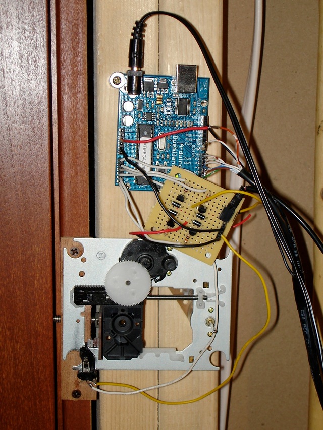
After tearing down an old CD player, I was inspired by the CD laser scanning assembly to build a door lock for my subterranean lab. The assembly has two motors: one for turning the CD (I’m not using this one) and one for slowly moving the laser across the CD’s surface. This second motor provides a nice linear motion that I wanted to use to build an electronically-controlled dead bolt lock for my lab.
Here’s the assembled lock. The circuit board in the middle is an H-bridge circuit I built to allow the motor to move in both directions. There are two position sensing switches so the Arduino senses when the motor has reached its limit in either direction. A 9V power supply powers the Arduino board, and a separate 5V supply drives the motor through the H-bridge. The dead bolt is literally a bolt — connected to the assembly with a piece of scrap circuit board — that travels through the door jamb and into the door.
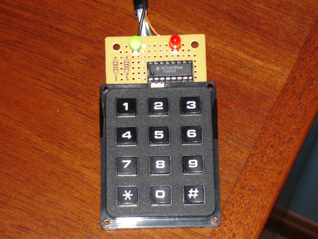
The black CAT5 cable connected to pins 2-8 goes through a small hole in the wall (under a desk) to the keypad on the outside of the lab (I wasn’t sure I wanted to permanently mount the keypad in the wall). The user types in the correct code and presses the # key to open or close the lock. The green LED indicates the door is unlocked. Red indicates locked. Let’s see the lock in action. (While recording, I gave instructions to my son to lock and unlock using the keypad off camera.)
Reading the keypad is by far the most complicated thing in the Arduino code below. They keypad has 12 keys but only 10 wires. Reading the keypad is not as simple as checking to see which of the 12 switches is closed. The keys must be constantly scanned to see which if any keys are depressed. Scanning the keypad is done by multiplexing through 6 of the wires on the keypad, alternately setting them LOW and then checking the other 4 wires (blue, green, yellow, red) on the keypad to see if a button is pressed.
A shift register on the keypad lets me control 8 outputs with only 3 Arduino pins: the latch pin, clock pin and data pin. The eight outputs are 6 multiplexed wires of the keypad plus one for each LED. The total number of wires running to the keypad is 3 for the output (latch, clock, data), 4 inputs, 5V, and GND. That’s 9 total, and since CAT5 has only 8 wires, I have the 9th wire (GND) taped to the CAT5. Hey, it got the job done.
#define LATCH_PIN 2
#define CLOCK_PIN 3
#define DATA_PIN 4

// Keypad inputs (colors are keypad wires, not cat5 wires)
#define BLUE_PIN 5
#define GREEN_PIN 6
#define YELLOW_PIN 7
#define RED_PIN 8

// PNP transistors.  LOW to activate.
#define Q1 17
#define Q2 19

// NPN transistors.  HIGH to activate.
#define Q3 16
#define Q4 18

#define LOCK_LIMIT_SWITCH_PIN 15  // long wires
#define UNLOCK_LIMIT_SWITCH_PIN 14

#define LOCKED 0
#define UNLOCKED 1
#define LOCKING 2
#define UNLOCKING 3

#define NO_SCAN 0xFC
#define BLACK 0x80
#define WHITE 0x40
#define GRAY 0x20
#define PURPLE 0x10
#define ORANGE 0x8
#define BROWN 0x4
#define GREEN_LED_ON 0x2
#define RED_LED_ON 0x1

#define NO_KEY -1
#define STAR 10
#define POUND 11

int state;
byte greenLED = 0;
byte redLED = RED_LED_ON;
int lastKey = -1;

#define MAX_GUESS 10
#define COMBO_LENGTH 4

int code[COMBO_LENGTH] = {5, 6, 1, 8};
int guess[MAX_GUESS];
int guessIndex = 0;

void setup() {
  pinMode(LATCH_PIN, OUTPUT);
  pinMode(CLOCK_PIN, OUTPUT);
  pinMode(DATA_PIN, OUTPUT);

  pinMode(BLUE_PIN, INPUT);
  digitalWrite(BLUE_PIN, HIGH); // set pull-up resistor
  pinMode(GREEN_PIN, INPUT);
  digitalWrite(GREEN_PIN, HIGH); // set pull-up resistor
  pinMode(YELLOW_PIN, INPUT);
  digitalWrite(YELLOW_PIN, HIGH); // set pull-up resistor
  pinMode(RED_PIN, INPUT);
  digitalWrite(RED_PIN, HIGH); // set pull-up resistor

  pinMode(Q1, OUTPUT);
  pinMode(Q2, OUTPUT);
  pinMode(Q3, OUTPUT);
  pinMode(Q4, OUTPUT);

  pinMode(UNLOCK_LIMIT_SWITCH_PIN, INPUT);
  digitalWrite(UNLOCK_LIMIT_SWITCH_PIN, HIGH); // set pull-up resistor

  pinMode(LOCK_LIMIT_SWITCH_PIN, INPUT);
  digitalWrite(LOCK_LIMIT_SWITCH_PIN, HIGH); // set pull-up resistor

  unlock();

}

void loop() {
  if ((isUnlocked()) && (state == UNLOCKING)) {
    stop();
    state = UNLOCKED;
  }
  if ((isLocked()) && (state == LOCKING)) {
    stop();
    state = LOCKED;
  }

  if ((state != UNLOCKING) && (state != LOCKING)) {
    int n = scanKeypad();
    if (n != lastKey) {
      // something changed
      if (n == NO_KEY) {
        // key released
        processKey(lastKey);
      }
      lastKey = n;
    }
  }
}

int scanKeypad() {

  writeData((NO_SCAN ^ BLACK) | redLED | greenLED);
  if (digitalRead(BLUE_PIN) == LOW) {
    return POUND;
  }
  if (digitalRead(GREEN_PIN) == LOW) {
    return 0;
  }
  if (digitalRead(YELLOW_PIN) == LOW) {
    return STAR;
  }

  writeData((NO_SCAN ^ WHITE) | redLED | greenLED);
  if (digitalRead(BLUE_PIN) == LOW) {
    return 9;
  }
  if (digitalRead(GREEN_PIN) == LOW) {
    return 8;
  }
  if (digitalRead(YELLOW_PIN) == LOW) {
    return 7;
  }

  writeData((NO_SCAN ^ GRAY) | redLED | greenLED);
  if (digitalRead(YELLOW_PIN) == LOW) {
    return 4;
  }

  writeData((NO_SCAN ^ PURPLE) | redLED | greenLED);
  if (digitalRead(BLUE_PIN) == LOW) {
    return 6;
  }
  if (digitalRead(GREEN_PIN) == LOW) {
    return 5;
  }
  if (digitalRead(YELLOW_PIN) == LOW) {
    return 2;
  }

  writeData((NO_SCAN ^ ORANGE) | redLED | greenLED);
  if (digitalRead(RED_PIN) == LOW) {
    return 3;
  }

  writeData((NO_SCAN ^ BROWN) | redLED | greenLED);
  if (digitalRead(RED_PIN) == LOW) {
    return 1;
  }

  return NO_KEY;
}

void processKey(int k) {
  if ((k != POUND) && (k != STAR)) {
    guess[guessIndex++] = k;
    if (guessIndex == MAX_GUESS) {
      clearGuess();
      blinkRed(3);
    }
  }
  if (k == POUND) {
    if (guessIsCorrect()) {
      if (state == LOCKED) {
        greenLED = GREEN_LED_ON;
        redLED = 0;
        unlock();
      } else {
        if (state == UNLOCKED) {
          greenLED = 0;
          redLED = RED_LED_ON;;
          lock();
        }
      }
      blinkGreen(3);
      clearGuess();
    } else {
      clearGuess();
      blinkRed(3);
    }
  }
}

void clearGuess() {
  guessIndex = 0;
  for(int i=0; i < MAX_GUESS; i++) {
    guess[i] = -1;
  }
}

boolean guessIsCorrect() {
  for(int i=0; i < COMBO_LENGTH; i++) {
    if (guess[i] != code[i]) {
      return false;
    }
  }
  return true;
}

void blinkRed(int n) {
  for(int i=0; i < n; i++) {
    writeData(NO_SCAN);
    delay(100);
    writeData(NO_SCAN | RED_LED_ON);
    delay(100);
  }
}

void blinkGreen(int n) {
  for(int i=0; i < n; i++) {
    writeData(NO_SCAN);
    delay(100);
    writeData(NO_SCAN | GREEN_LED_ON);
    delay(100);
  }
}

void writeData(byte data) {
  digitalWrite(LATCH_PIN, LOW);
  shiftOut(DATA_PIN, CLOCK_PIN, MSBFIRST, data);
  digitalWrite(LATCH_PIN, HIGH);
}

boolean isUnlocked() {
  return (digitalRead(UNLOCK_LIMIT_SWITCH_PIN) == LOW);
}

boolean isLocked() {
  return (digitalRead(LOCK_LIMIT_SWITCH_PIN) == LOW);
}

void unlock() {
  digitalWrite(Q2, HIGH);  // OFF
  digitalWrite(Q3, LOW);   // OFF
  digitalWrite(Q1, LOW);   // ON
  digitalWrite(Q4, HIGH);  // ON
  state = UNLOCKING;
}

void lock() {
  digitalWrite(Q1, HIGH);  // OFF
  digitalWrite(Q4, LOW);   // OFF
  digitalWrite(Q2, LOW);   // ON
  digitalWrite(Q3, HIGH);  // ON
  state = LOCKING;
}

void stop() {
  digitalWrite(Q1, HIGH);  // OFF
  digitalWrite(Q2, HIGH);  // OFF
  digitalWrite(Q3, LOW);   // OFF
  digitalWrite(Q4, LOW);   // OFF
}


hi ..
I was amazed to see that your application for the program .. I’m from Indonesia are conducting a thesis on microcontroller chance I accidentally found this website and was very interested to explore a demo application that you created for me to learn on my thesis. I am very grateful to you if I can find Schematic Controlled Lock with Keypad, if I can find it above? thank you for sharing info ..
greeted by
Abenk Mursal
just info, I can not access the video or movie that you display in the website of the controlled lock with keypad.
thanks
you can put the project schematic. i can´t see the connections on the board and the arduino and servos
hi…
i am from india . i am very intrested in this project . i am very great full to you if you can send me the schematic of this project.
thank you..
hi..
I am from the south pacific islands (a little country known as Vanuatu)and I am also very interested with this project, i will be very grateful if you can send me the schematic diagram. Thank u very much!
i would really really want to try this out its so cool…. please sent me the schematics and the details if you may. thanks
Thank for this project.I am from Africa, Ghana.I will like to experiment this Project as well.Can will kindly send me the systematic diagram.Thank you
i would really really want to try this out its so cool…. please sent me the schematics and the details if you may. thanks
sir pls send the schematic diagram for my project . . .
Podia-me enviar os planos de montagem pf, estou muito interessado em fazer.
Obrigado
Respected Sir,
I intend to do this project for my M.Sc IVth semester.I need schematic circuit diagram of this project. I would be grateful to you If you send the ckt diagram of this project.
There’s no schematic — I did this project many years ago. From the description, you should be able to design your own project.
Great job! It has given me an idea on what to do with all of the trashed CD drives that seem to breed in the basement.
I ahve to laugh at the requests from Asia and Africa about people working on theses, or a MS, and they can’t figure out a simple schematic or how to use google.
Thanks for sharing your idea :)