Difficulty Level = 5 [What’s this?]
UPDATE: Also see this project for an easy way to display a temperature reading: Digit Shield Temperature Display.
A while back, I did a wireless temperature sensor project using XBee radios. XBee radios are really powerful devices with good reliability and the ability to read and transmit sensor readings without a microcontroller. BUT, they are difficult for people to configure, the documentation is hard to understand, and it’s really difficult to parse the API data packets at the receiving station. So I decided to try the same project using inexpensive RF devices. I used a 434MHz transmitter ($4) and receiver ($5) from Sparkfun, and had great success with these cheap devices. I also used a simple LM34 Fahrenheit temperature sensor, two Arduinos (one was a homemade breadboard version), and a two-digit LED display to show the temperature at the receiver end.
The Receiver
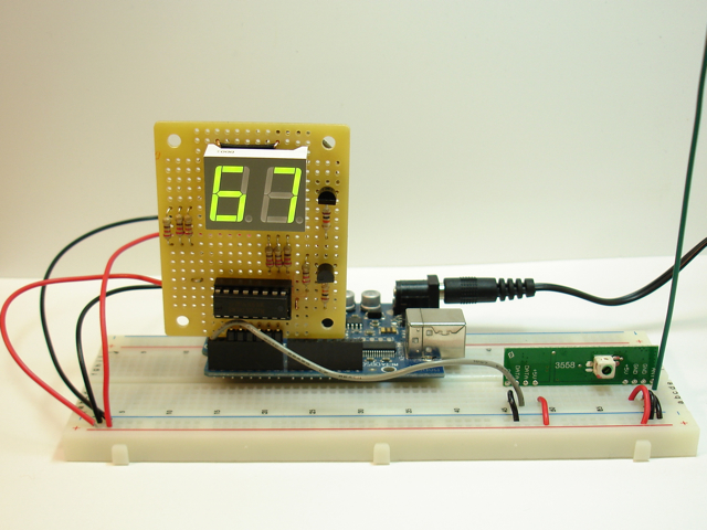
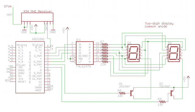
I used a single 74LS247 BCD to 7-segment driver chip for the display. The segment pins of the two digits are connected together, so I need to multiplex between the digits to show only one at a time. The multiplexing is so fast, there’s no flicker. The segments have common anodes and I used two PNP transistors to provide current to the anodes. Don’t ever drive the anodes directly from an Arduino output pin because it’s too much current!The RF receiver’s data pin is connected to the RX pin on the Arduino so we can just use the Serial library to read data at a slow 1200 bps. That is fast enough for temperature sensor readings. A 17cm antenna (the green wire) is attached to the ANT pin on the RF receiver.
Another important note is that the multiplexing between the two display digits is handled in an interrupt handler. The loop() code never has to do anything with the display. Timer2 is configured to fire an interrupt when the timer2 counter overflows, so the ISR near the end of this code runs about every 2ms and simply toggles which display is active. This is fast enough to provide perfectly smooth display without any fuss. All the register manipulation in the setup() method is the configuration of Timer2. I really like this way of handling the multiplexing automatically. You can download the code here.
#define PACKET_HEADER_SIZE 3
#define PAYLOAD_SIZE 1
#define CHECKSUM_SIZE 1
#define PACKET_SIZE (PACKET_HEADER_SIZE + PAYLOAD_SIZE + CHECKSUM_SIZE)
#define ADDR 1

byte temp = 0;
byte d1; // left digit
byte d2; // right digit
byte digitToggle = 0;

const byte packetHeader[PACKET_HEADER_SIZE] = {0x8F, 0xAA, ADDR};

void setup()
{
  Serial.begin(1200);

  for(int i=2;i<=7;i++) {
    pinMode(i, OUTPUT);
  }
  digitalWrite(6, HIGH);
  digitalWrite(7, HIGH);

  // Disable the timer overflow interrupt
  TIMSK2 &= ~(1 << TOIE2);

  // Set timer2 to normal mode
  TCCR2A &= ~((1 << WGM21) | (1 << WGM20));
  TCCR2B &= ~(1 << WGM22);

  // Use internal I/O clock
  ASSR &= ~(1 << AS2);

  // Disable compare match interrupt
  TIMSK2 &= ~(1 << OCIE2A);

  // Prescalar is clock divided by 128
  TCCR2B |= (1 << CS22)  | (1 << CS20);
  TCCR2B &= ~(1 << CS21);

  // Start the counting at 0
  TCNT2 = 0;

  // Enable the timer2 overflow interrupt
  TIMSK2 |= (1 << TOIE2);
}

void loop() {
  temp = readByte();
  setValue(temp);
}

byte readByte() {
  int pos = 0;
  byte val;
  byte c = 0;

  while (pos < PACKET_HEADER_SIZE) {
    while (Serial.available() == 0); // Wait until something is available
    c = Serial.read();

    if (c == packetHeader[pos]) {
      if (pos == PACKET_HEADER_SIZE-1) {
        byte checksum;

        // Wait until something is available
        while (Serial.available() < PAYLOAD_SIZE + CHECKSUM_SIZE);
        val =  Serial.read();
        checksum =  Serial.read();

        if (checksum != (packetHeader[0] ^ packetHeader[1] ^ packetHeader[2] ^ val)) {
          // Checksum failed
          pos = -1;
        }
      }
      pos++;
    } else {
      if (c == packetHeader[0]) {
        pos = 1;
      } else {
        pos = 0;
      }
    }
  }
  return val;
}

void setValue(byte n) {
  d1 = n / 10;
  d2 = n % 10;
}

void setOutput(byte d) {
  // This is more complex because the 74LS247 inputs are on
  // nonconsecutive Arduino output pins (for ease of soldering).
  PORTD &= ~0x3C; // turn off digital pins 2-5
  if ((d & 0x1) > 0) {
    // 74LS247 input A connected to Arduino pin 5
    PORTD |= (1 << PORTD5);
  }
  if ((d & 0x2) > 0) {
    // 74LS247 input B connected to Arduino pin 2
    PORTD |= (1 << PORTD2);
  }
  if ((d & 0x4) > 0) {
    // 74LS247 input C connected to Arduino pin 3
    PORTD |= (1 << PORTD3);
  }
  if ((d & 0x8) > 0) {
    // 74LS247 input D connected to Arduino pin 4
    PORTD |= (1 << PORTD4);
  }
}

// Interrupt service routine is invoked when timer2 overflows.
ISR(TIMER2_OVF_vect) {
  TCNT2 = 0;
  if (digitToggle == 0) {
    PORTD |= (1 << PORTD7);  // turn off digit 2
    setOutput(d1);
    PORTD &= ~(1 << PORTD6); // turn on digit 1
  } else {
    PORTD |= (1 << PORTD6);  // turn off digit 1
    setOutput(d2);
    PORTD &= ~(1 << PORTD7); // turn on digit 2
  }
  digitToggle = ~digitToggle;
}
The Transmitter
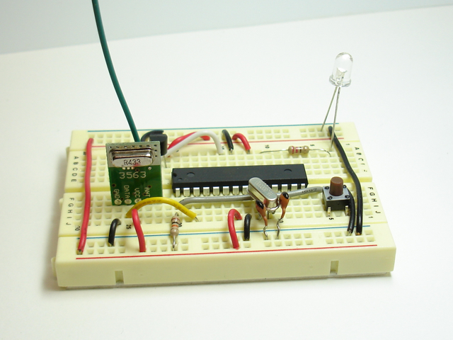
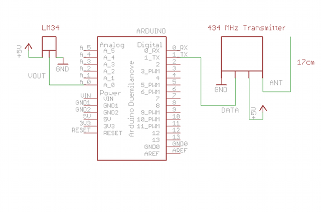
The unfortunate thing about using the RF transmitter is that it's a lot dumber than an XBee radio (but a lot cheaper, too). It has no ability to read the voltage on a pin and transmit it, so I had to use a microcontroller of some sort. At first I wanted to use an ATtiny13, but it has no UART for the serial transmission control. Then I wanted to use my ATtiny2313 which does have a UART, but doesn't have an analog to digital converter (ADC)! The smallest AVR microcontroller that I own that has both ADC and UART is the ATmega328. At this point I figured I might as well use a full-blown Arduino. I don't have two Arduinos so I built a breadboard version for use at the transmitter. You can just use a regular Arduino if you have one handy, or team up with a friend who has one.An LM34 temperature sensor outputs a variable voltage depending on the temperature. The mapping is extremely simple: 10mV for every Fahrenheit degree. So, at 72 degrees F, the output is 720mV. The Arduino TX pin is simply connected to the data pin on the transmitter.
Here's the schematic. There's an LED attached to pin 13 that I blink every time a sensor reading is transmitted (not shown in schematic).
#define SENSOR_ANALOG_PIN 0
#define LED_PIN 13
#define PACKET_HEADER_SIZE 3

#define ADDR 1

const byte packetHeader[PACKET_HEADER_SIZE] = {0x8F, 0xAA, ADDR};

byte temp;

void setup() {
  Serial.begin(1200);
  pinMode(LED_PIN, OUTPUT);
}

void loop() {
  digitalWrite(LED_PIN, HIGH);
  readTemp();
  writeByte(temp);
  digitalWrite(LED_PIN, LOW);
  delay(1000);
}

void readTemp() {
  byte reading = analogRead(SENSOR_ANALOG_PIN);
  int mv = ((float)(reading/1023.0)) * 5000;
  temp = mv / 10;
}

// Sends an unsigned int over the RF network
void writeByte(byte val) {
  byte checksum = (packetHeader[0] ^ packetHeader[1] ^ packetHeader[2] ^ val);
  Serial.write(packetHeader, PACKET_HEADER_SIZE);
  Serial.write(val);
  Serial.write(checksum);
}
That's all there is to it! This setup allowed me to transmit sensor readings reliably throughout my home, especially with a 17cm (1/4 wavelength of 434Mhz signal) antenna at the transmitter and receiver.

WOW.. it’s really cool project!!
i am currently developing automatic clothes line using RF and connected it with rain detector… I’ just modified RF car controller to see whether it works or not.. :D
if it works, after that i will try to connect it with the system.. maybe c# or vb..
i’m looking forward to read your respond ;D
Great project – I remember checking you out a while back, but came across your site again via today’s Make: post on the Hackvision. Congrats!
Anyways, just wanted to clarify about the antenna since you don’t go into much detail. I assume it’s the green insulated wire at both the receiver and transmitter – but for optimal range, do you find one type of wire better than another (ie. stranded vs solid, insulated vs bare)?
@Steve,
Yes, it’s the green wire. I didn’t experiment with different types of wire. I suspect that stranded will work just as well as solid, but I’m not an RF expert. The length is 17cm and I think that multiples of that (e.g. 34cm) will also provide good reception. Using the antenna helped a lot. Experiment!
Hi, I am fairly new at electronics and I am just wondering why you have resistors on the cathode AND anode sides of the 7-seg displays?
Also where do you ground the 7-seg displays, the schematic doesn’t seem to show this anywhere. Like I mentioned above, I’m new to electronics so forgive me if I’m simply misunderstanding the schematic…
There are resistors on the cathodes (each segment). There are not resistors on the anodes. There is a 10K resistor on the base of the transistor, but the current on the anode is not limited by a resistor.
The cathodes are the ground of each LED. The 74LS247 chip sinks current.
Hi, We are working on this project but we are confuse with transmission. What kind of data process by Micro controller. and what kind of data transmitted by transmitter. Is it transmitting ASCII?
No, it’s not transmitting the temperature as ASCII characters. It’s transmitting the temperature reading as a single byte. Look at the transmitter code. The line is “writeByte(temp);”
hi, i am also working on this project but i have a couple of questions firstly i want to know that on transmitter side are we converting analog value to decimal or hexadecimal before transmitting? and second, how we display a single byte on LED display?
could you please help me with this
The analog value is stored as a byte and is transmitted. Decimal and hexadecimal are notation for humans. Computers use binary, so your question doesn’t make much sense. The byte holds a value and that value is transmitted.
A byte has 8 bits, so it can hold a value of 0-255. The value of the byte represents the temperature. If the temperature is 68 degrees, then the value in the byte is 68. The receiver displays that value by figuring out what each digit should be. Does that make sense? Just read the code — it’s all there.
hi, i need to know that how we are displaying the value 68 on display?
could you explain the whole process please….
I provided the schematic and all the code, and there are comments in the code. Did you spend time studying the code? If you want to understand how something works, you need to invest some time into it, right?
i tried to understand the code but i didn’t get that part
void setOutput(byte d) {
// This is more complex because the 74LS247 inputs are on
// nonconsecutive Arduino output pins (for ease of soldering).
PORTD &= ~0x3C; // turn off digital pins 2-5
if ((d & 0x1) > 0) {
// 74LS247 input A connected to Arduino pin 5
PORTD |= (1 < 0) {
// 74LS247 input B connected to Arduino pin 2
PORTD |= (1 < 0) {
// 74LS247 input C connected to Arduino pin 3
PORTD |= (1 < 0) {
// 74LS247 input D connected to Arduino pin 4
PORTD |= (1 << PORTD4);
}
}
Could you help me with this please…
Arduino digital pins 5, 2, 3, and 4 are connected to the 74LS247 input pins A, B, C, and D respectively. To make the 74LS247 display a digit, you set the input pins A, B, C, D to the binary representation of the number. To display a ‘6’, you set A low, B high, C high, and D low. Because the number 6 is 0110 in binary. See the 74LS247 data sheet for the relationship between the digits and the input pins. http://www.jameco.com/Jameco/Products/ProdDS/47247.pdf
thanks…
could anyone tell me the meaning of this line “const byte packetHeader[PACKET_HEADER_SIZE] = {0x8F, 0xAA, ADDR};” Please
@Mark,
it declares an array of bytes called “packetHeader” of size 3, and the contents are assigned. Each packet transmitted has a constant header at the beginning with fixed values so that the sender and receiver can sync up. The 3rd byte is the address of the packet’s destination.
Hi Michael, I think your schematic is missing pin 8 of the 74LS247 going to ground? This is what confused me in my last post:
> Also where do you ground the 7-seg displays, the schematic doesn’t seem to show this
> anywhere. Like I mentioned above, I’m new to electronics so forgive me if I’m simply
> misunderstanding the schematic…
By the way, thank you for updating the schematic to show the resistors – much easier to follow and understand!!
Hi Michael, I managed to replicate your project using a 4-digit 7-segment display, it works beautifully! There was a bug that took me a while to figure out in your digit toggling:
This turns digit 2 on, not off:
PORTD |= (1 << PORTD7); // turn off digit 2
This turns digit 1 off, not on:
PORTD &= ~(1 << PORTD6); // turn on digit 1
Julian, there’s no bug in my code for the circuit I used. I’m using PNP transistors on the anodes, so they are active LOW, not HIGH. To turn on a digit, set the pin LOW. To turn it off, set it HIGH. Did you use PNP transistors on the anodes?
@Michael you are 100% correct, of course. It seems that the “S8050 PNP General Purpose Transistors” I ordered from Futurlec are actually NPN transistors (serves me right for trying to get away with 5c per transistor).
Regardless, I switched that part of the code around to work for my (apparently) NPN transistors and there doesn’t seem to be a problem. Which leads me to ask, what is the advantage (if any) of using PNP transistors in this part of the circuit?
Ok, that makes sense. Typically you would use a PNP transistor to source current. You would use an NPN transistor to sink current. The general rule is that you tie the emitter to a fixed voltage. So when using a PNP as I did, the emitter is tied to the 5V source and the collector is connected to the LED anode. With your NPN, the collector is tied to the 5V line and the emitter is not connected to a fixed voltage but is “floating”. I just follow the general rule of making sure the emitter is the one tied to the voltage, whether it be 5V for sourcing current with a PNP, or GND for sinking current with a NPN. Hope that helps.
Thanks Michael, this topic has led me to learn a lot more about transistors, and I’m glad I now have a basic understanding (I think)! Just to confirm that I’m on the right track, the reason the emitter is usually connected to the fixed voltage is because of the small leakage between the base and the emitter when the transistor is off, correct? So that would mean that in my circuit, I have a very small amount of current flowing through my segments where their digits are supposed to be “off”.
I’m not an expert, but I think you might be right. There must be a bit of current leaking from emitter to the base which is held low. If you use PNP, you’ll be in great shape.
Hi Michael!
Great project and exactly what I’m currently planning to do. Really smart not to use two fully equipped Arduinos and, morevoer, to stick to cheap RF links instead of ZigBee radio technique.
But I’m still thinking about your transmitter layout: is this a 16.000 kiloOhm resistor below the AtMega328 … as here is “16.000.000” printed on its surface!? And what are these two
orange parts with the black color on it – capacitors? Can you please say (i) how these three elements are wired because the image is hiding some info on that (unfortunately, the plan doesn’t contain these elements either) and (ii) why you have to use them in your setup at all!
Thanks a lot and
Regards
Jan: The transmitter is a breadboard Arduino. The components you ask about are the 16MHz crystal and the 22pF capacitors. If you google for “breadboard Arduino” you’ll find many tutorials that teach you how to build an Arduino on a breadboard with a few components. You can just use a regular Arduino, too, if you have an extra. I didn’t so I built one.
Thanks, Michael!! You helped me a lot, appreciate!
Can your project work with feeds from multiple temperature sensors/rf sources or is this a one-to-one link up?
Thanks
The software could be modified to receive from different receivers (note that the transmitter has an ADDR identifier). But I think the signals would interfere with one another since they are on the same frequency…
Hi Michael,
Thanks for this tutorial…your ptoject is great !
I did your first version (zigbee) with a lot of success but with the modification written by ilium007 (http://www.arduino.cc/cgi-bin/yabb2/YaBB.pl?num=1264655063/15) because I did’t have the two 7 led segments at this time and I use a TMP36 sensor…so cool !
Now I have done the two boards as describe in this tutorial, everything is running fine, communication radio link is OK, Serial.print(temp, DEC) is OK on the emitter side but the two 7 led segments do not print the same value.
Emitter:
void readTemp() {
byte reading = analogRead(SENSOR_ANALOG_PIN);
int mv = ((float)reading) * (5000/1024);//TMP36 plug to +5v
temp = (mv – 500) / 10; //DC offset for TMP36
Serial.println(temp, DEC); //it prints 20°C
}
Receiver:
void loop() {
temp = readByte();
setValue(temp);
Serial.println(temp, DEC);//it prints 207 and the Led segments show 47
}
Your help should be cool…
Hmm. I can’t really tell what is wrong. How are you using the XBee and Serial at the same time? How are you transmitting the temperature reading? I don’t see the transmission….
Hi Michael,
sorry for the confusion. The xbee project has been done before (as describe in your tutorial) and it’s working great. What I’m trying to do now is your new version of wireless temperature sensor, using RF Transmitter/Receiver. This problem makes me crazy, I really don’t know why I get 46 or 47 on the Led Segments instead of 20 (my room temperature). I’ve controled my TMP36 sensor and I’m sure it’s OK with the calcul describe in the void readTemp just pasted above. If I bypass the calcul and just write temp = 20; instead of temp = (mv – 500) / 10;, the led segment prints 20. I mean that the RF link seems to work.
I’m using this RF materials:http://radiospares-fr.rs-online.com/web/p/modules-rf-misc/6172072/
http://radiospares-fr.rs-online.com/web/p/modules-rf-misc/6172044/
Could it be no compatible ?
you can see a photo of my boards just here: http://www.arpege-studio.com/RF/
Really lost…
Oh, I see. Sorry I was confused. The problem is that your variable “reading” needs to be declared as an int, not a byte. The value of an analog read won’t fit in a byte. So your reading was too small, then when you subtract 500 from it, it goes negative. So “temp” was negative. Then you wrote it across the RF link and read it as a byte, and this was then interpreted as a 207.
And the divisor in your formula should be 1023, not 1024. The maximum sensor value is 1023, so you want a reading of 1023 to give a result of 5000 mV. If you use 1024, then the formula produces a slightly wrong value.
Try this:
void readTemp() {

    int reading = analogRead(SENSOR_ANALOG_PIN);

    int mv = ((float)reading) * (5000/1023);  //TMP36 plug to +5v

    temp = (mv – 500) / 10;   //DC offset for TMP36

    Serial.println(temp, DEC);

}
You’re welcome ! Thanks for your help.
Unfortunltely it does not change anything..Argghhh !
For fun and to confirm RF link is OK, I made a counter (boards were 4 meters from each other): http://www.arpege-studio.com/RF/
I’ll try tomorrow to connect an LCD on the emitter board in order to print locally the result contained in temp.
Damn it will work…!
Hi Michael !
I finally found what caused the bug but I can not find a solution to solve it.
First, I did a test with my LCD on the transmitter board and the temperature still showed 207 on the LCD and 47 on the Segments Led. So I unplugged the ground of the transmitter and the miracle happens. My LCD displays 22°C…So good…and of course nothing on the segments Led (no ground)!
So I tried to use a separate power supply for transmitter but with no common ground, the transmitter does not work..Arrrrgh ! And if I link the grounds of the 2 power supply, the transmitter works but the temperature value becomes 207 and 47 ! I’m stuck.
If you have an idea :-)))
I think you should break the problem down by printing (on LCD) the value of ‘reading’ on the LCD. Then disconnect the ground and see if ‘reading’ changes.
Despite the new evidence about the ground, my intuition tells me there is still a data type issue of some kind. You had said that setting “temp = 20;” made everything work, but using your calculation gave the bad values. That’s a big clue.
Break the problem down into tiny steps. First display ‘reading’. Then ‘mv’. Then ‘temp’.
OK, here are the results
Without the transmitter:
reading: 165, mv: 656, temp: 16
With the Transmitter:
reading: 15, mv: 60, temp: 212
I’ve also check voltage at the output of the 7805: 5.15V
Between: pin 20 & 22 | 6 & 7 of the ATMega328P-PU: 5.15V
Between: pin 1 & 3 of the TMP36: 5.15V
I ask myself if this transmitter is compatible with the arduino in this state. In the datasheet they talk about the RF600E Encodeur. http://docs-europe.electrocomponents.com/webdocs/0248/0900766b802489bb.pdf
Thanks again
Ok, it looks like analogRead isn’t working correctly when your transmitter is connected. That makes no sense to me…
Hi Michael,
Finally it works ! I added a digital output to control turning on and off the transmitter. In this way, analogRead is working correctly.
void setup() {
…
pinMode(transmitter, OUTPUT);
digitalWrite(transmitter, LOW);
…
}
void loop() {
digitalWrite(LED_PIN, HIGH);
readTemp();
digitalWrite(transmitter, HIGH);
delay(1000);
writeByte(temp);
digitalWrite(LED_PIN, LOW);
delay(1000);
digitalWrite(transmitter, LOW);
}
http://www.arpege-studio.com/RF/
Hope this can help others.
Thanks for your help
Hi Michael;
I made an evolution to your project in order to display negative temperature. So, I added a third digit LED display (Anode to Pin 8, G segment to Pin 9).
Here is the code (sorry if this is not optimized)
const int d3 = 8;
const int negatif = 9;
void setup()
{
…
pinMode(d3, OUTPUT);
pinMode(negatif, OUTPUT);
digitalWrite(d3, LOW);
digitalWrite(negatif, HIGH);
…
}
void loop() {
temp = readByte();
int temperature = temp;
if (temperature >= 157) { // -99°C = 157 even if TMP36 Max = -40 => 216
digitalWrite(negatif, LOW);
temp = (temperature * -1);
setValue(temp);
}
else {
setValue(temp);
}
}
http://www.arpege-studio.com/RF/
Really enjoyed this project !
Hi Michael,
sorry to come back again for a few more questions.
What works: AM Transmitter/Receiver at 1200 baud with my DIY arduino board or the official Uno for the Receiver part…great ! FM Transmitter/Receiver at 9600 baud with my DIY arduino board for the Receiver part….great too !
What does not work: FM Transmitter/Receiver at 9600 baud (or other values) with the official Uno for the receiver part…the serial does not receive anything ! So I tried with a mega2560 but it’s worse…the led segments do not turn on.
Thanks again.
Vince, I really have no idea. I don’t have that hardware, and I don’t know how I can debug remotely…
Hi Michael,
Just to say thanks for the idea, I was looking for a way to get power use or temperature from remote sensors in a domestic situation i.e. low cost. Using the RF module with a small pic for myself works great.
Thanks again
Hi Michael I’m a newbie in using arduino and I just wanna ask if your code works for a pair of transmitter/receiver of 315Mhz, because I did the all thing and I only got ceros from the displays. I am working with a pair of arduino uno, I just made a change in the transmitter program, because I’m using the LM35 so instead of doing this:
byte reading = analogRead(SENSOR_ANALOG_PIN);
int mv = ((float)(reading/1023.0)) * 5000;
temp = mv / 10;
I did this
byte reading = analogRead(SENSOR_ANALOG_PIN);
temp=(5.0 * reading * 100.0)/1023.0;
Any recommendation wil be appreciated
Héctor, I suppose it should work with 315MHz devices. First, I would try to just send a fixed number across the link to see if that works. Then add the sensor readings and calculation.
HI Michael, thank for your answer, but i have another question, what does this part of the program do?
// Disable the timer overflow interrupt
TIMSK2 &= ~(1 << TOIE2);
// Set timer2 to normal mode
TCCR2A &= ~((1 << WGM21) | (1 << WGM20));
TCCR2B &= ~(1 << WGM22);
// Use internal I/O clock
ASSR &= ~(1 << AS2);
// Disable compare match interrupt
TIMSK2 &= ~(1 << OCIE2A);
// Prescalar is clock divided by 128
TCCR2B |= (1 << CS22) | (1 << CS20);
TCCR2B &= ~(1 << CS21);
// Start the counting at 0
TCNT2 = 0;
// Enable the timer2 overflow interrupt
TIMSK2 |= (1 << TOIE2);
}
I don't understand anything, so i would be a good thing if you can explain it line per line
or give me the equivalent mnemonics for PIC please
Hector, I DID explain what each line does. See the comments? If you don’t understand the ATmega328 then you can read the datasheet, but my comments tell exactly what I was doing to the microcontroller. I don’t know PIC, so I can’t explain how you can do it with a PIC.
my name is sahil surani.i am making simple RFID Tx and Rx ,i want
to just send simple 1,2,a,b…… or some short message like hi
,hello,sahil….etc. i want simple program (software)
that transmit data or message from Tx to Rx and display on lcd the
message can be in code(software).can any one please send me code or software.my email is suranisahil786@gmail.com
thank you in advance and i am thinking of your positive reply.
thank you
hi, i am new to this arduino……
i tried receiver ur prgm in arduino atmega8 controller…..
it is showing some error in using TIMSK2,TCCR2A,TCCR2B,WGM……
can u say me the alternative of that line.pls…..
Very cool project and nice job of explaining everything.
I was wondering what line of sight range you were able to get with the 17cm ant ?
thanks ric
I don’t recall, but maybe 20m.
Cool site u got here…
May I ask, what simulation software did u use to do simulation?
What simulation? I didn’t use simulation software.
No. I’m just asking since I saw the schematic..
The schematic u draw using what?
The schematic is drawn using Cadsoft EAGLE.
Well sir..Thank you very much for ur respond..:)
Hi Michael,
Great little project. I am just starting out on transmitting temperature details back to a display. I was wondering if the hardware you are using here is capable of being addressable so that a single bas station might be able to receive temperatures from several transmitters? I understand there will need to be changes made to the setup etc but was just interested to know if you can achieve something like this with this hardware? I guess the next logical step after that would be able to have multiple wireless displays that can display the temp from any remote sensor.
what are your thoughts on such a project? Is there any advice you would give or places to read up? I have seen many different projects on the web and using Xbee seems to be a favourite but adds to the cost etc.
Thanks
Ja
Jason: Yes, XBee radios can be configured to be in networks. You’ll need to carefully study the network setup using the Digi documentation for the particular radios you use. But yes, they have addresses.
Hello Michael,
I was looking at doing this project, and I was wondering exactly how you chose the frequency of your receiver and transmitter?
Thanks
434 MHz just happens to be a commonly used frequency for simple RF transmitters/receivers.
Michael,
I have question involving the antenna. Will the length of the antenna used in the project have the ability to transmit data to the receiver if they are, lets say one or two rooms apart? No cement walls or anything fancy, just dry wall. If not, do you have any ideas on how to get further range, directional antenna maybe?
Thanks
I think that an RF solution might work for that distance. It would be close, though. XBee digital radios have much further range and are more reliable.
I’m not really an expert in antenna design….
Helloo,
Great work.
Can I do the simulation of transmitter at any software?
If yes ,Please suggest some software and would be great if you could give the circuit of transmitter..
Dude, can you suggest a way on how to configure an external antenna? What do I have to do? Just add a wire? I didn’t get why should it be 1/4 of the wavelength :( Thanks!
Michael,
The 2 digit display you used was it a 18 pin display common anode correct?
Thanks
Yes, that’s correct. 18 pin, common anode.
Is there a way you would suggest testing this circuit? I have built the circuit completely and im getting a dim glow from the LEDS any suggestions on where to start?
Appreciate your input.