Difficulty Level = 2 [What’s this?]
The Digit Shield is a very easy-to-use Arduino shield that provides a digital readout for your Arduino projects. Some example projects are here.
One of my customers asked me about driving multiple Digit Shields from one Arduino. I had never thought of that, but the customer had the idea of using a single Arduino to display the X,Y,Z positions of a CNC router. I thought this was an intriguing idea, and with a little bit of experimentation and modification to the Digit Shield library, I was able to very easily accomplish this.
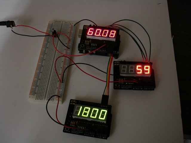
When a Digit Shield is on top of an Arduino, the pins used to control the shield are 2, 3, 4, and 5. In the picture above, this shield is displaying value “60.08”. If we connect another shield, we obviously have to use different Arduino pins to drive it. The second shield in the picture above (the one displaying “59”) is connected to Arduino pins 6, 7, 8, and 9. Of course, the wires still connect to pins 2, 3, 4, and 5 on the shield itself.
The 3rd shield in the picture displaying “1800” has its pins 2, 3, 4, and 5 connected to Arduino pins A3, A2, A1, and A0 respectively. In the code, analog pins are used as digital pins by referring to them as 17, 16, 15, and 14.
What about the code? I added a constructor for DigitShieldClass to the library so you can create new objects to represent the additional shields. The shield on the Arduino is still referenced as “DigitShield”, but the additional ones are referenced as “digitShield2” and “digitShield3”. Here’s how the shields are declared and initialized.
// Create a second Digit Shield connected to Arduino pins 6,7,8,9
// Connected to pins 2,3,4,5 on the shield, respectively.
DigitShieldClass digitShield2(6, 7, 8, 9);

// Create a third Digit Shield connected to Arduino pins 17,16,15,14 (A3,A2,A1,A0)
// Connected to pins 2,3,4,5 on the shield, respectively.
DigitShieldClass digitShield3(17, 16, 15, 14);

void setup() {
  // The static variable DigitShield refers to the default
  // Digit Shield that is directly on top of the Arduino
  DigitShield.begin();
  DigitShield.setPrecision(2);

  // Initialize the other two shields
  digitShield2.begin();
  digitShield3.begin();

  // set all values to 0
  DigitShield.setValue(0);
  digitShield2.setValue(0);
  digitShield3.setValue(0);
}
The full code example is called “MultiShieldExample” and is included in the Digit Shield library.
Also note that I’m providing power to the off-Arduino shields with a 7805 voltage regulator. The Arduino’s voltage regulator can deliver quite a bit of power, but it got rather warm when driving all these LEDs. So, in the picture above, there’s a 7805 which provides 5V to the 5V pins on the off-Arduino shields. Also make sure you connect all the grounds together.


Hello from Australia.
I am interested in knowing if i am able to connect at least 8 digital shield, they are essentially there as an instrument cluster measuring pressure, voltage and Temperature.
Thanks
Dominic Ryan
Western Australia
Each Digit Shield requires 4 pins, so it can only drive 3 Digit Shields. There are not enough pins on the Arduino to drive 8 shields. I would consider using I2C addressable displays for your application. See this: https://www.adafruit.com/categories/103