Difficulty Level = 7 [What’s this?]
I built a remote-controlled robotics platform using a 4WD mobile platform, an Arduino (Seeeduino Mega), an Adafruit motor shield, and two XBee radios for communication. There are also some super-bright white LEDs on the front for headlights. The point of the project was to show how an XBee radio can be used to send joystick sensor data without using a microcontroller on the remote.
The vehicle is very easy to control using a joystick and a couple of buttons to control the lights. First I’ll describe how the remote control unit works, then I’ll show how the vehicle was built.
The Remote
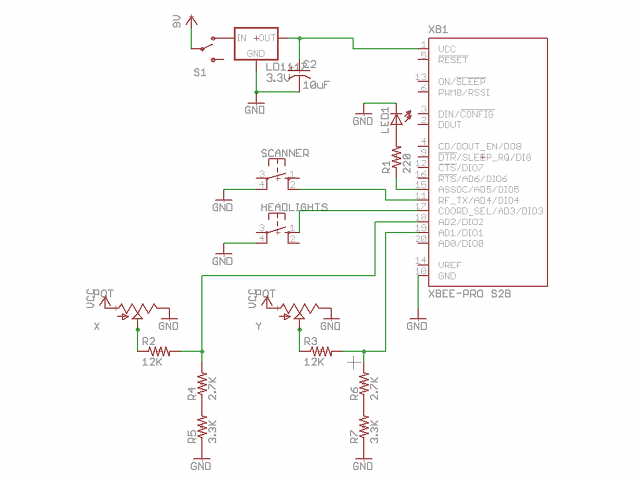
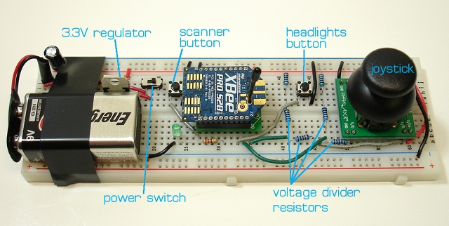
Here’s a picture of the remote control unit that I built on a breadboard. A Parallax joystick is used to control the vehicle, one button turns the headlights on/off, and another button puts the headlights in “scanner” mode, you know, like Kitt or like a cylon. The radio requires a 3.3V supply, but the analog pins cannot take more than 1.2V, so I used some precision resistors to form a voltage divider so that the analog input voltage was stepped down to less than 1.2V. Also note that the joystick is rotated 90 degrees so that it worked on a breadboard with this orientation.
To make this work, one radio needs to be running the “coordinator” firmware, and the other running the “router” firmware. In this project, the coordinator is on the vehicle and the router is on the remote control, but it should not really matter. It’s important that each radio be running the API mode firmware, not the AT/transparent firmware.
I used the X-CTU tool from Digi to write the appropriate firmware to the radios and configure them. If you have not done this before, this is not a good project to start with. It is best to start with 2 radios that you already have working together using the API firmware.
The XBee on the remote control unit is configured to send analog/digital sample packets every 100ms. Pins AD1 (pin 19) and AD2 (pin 18) are configured as analog inputs and are connected to the potentiometers in the joystick. Pins DIO3 (pin 17) and DIO4 (pin 11) are configured as digital inputs for the two buttons on the remote that control the lights on the vehicle. Here is a list of the configuration parameters that were set on the remote radio:
- AD1/DIO1 = 2 (configured as analog input)
- AD2/DIO2 = 2 (configured as analog input)
- AD3/DIO3 = 3 (configured as digital input)
- DIO4 = 3 (configured as digital input)
- IR = 0x64 (sample rate set to 100ms)
- PR = 0x1FFF (all pullup resistors enabled — this is the default)
This is a schematic of the remote control unit:
The Vehicle
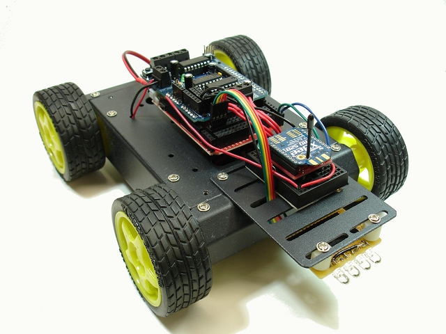
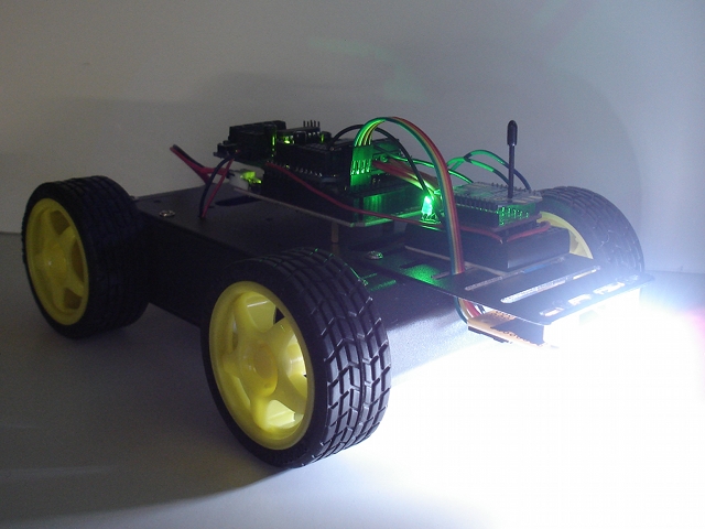
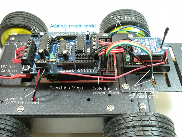
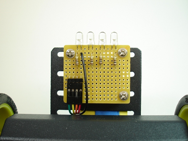
The wiring for the vehicle is fairly simple. Inside the 4WD platform are 5 AA batteries for powering the motors, and a 9V battery for the Arduino. I’m using a Seeeduino Mega because that’s what I had handy but any Arduino will work. The Adafruit motor shield is connected to the 4 DC motors inside the chassis. I used the 3.3V power supply on hte Arduino to power the XBee radio. The TX/RX lines of the radio are connected to the RX/TX pins on the Arduino. There’s a ribbon cable connecting 4 output pins to the LED headlights, and a ground wire running to the headlight assembly. Here is the bottom of the headlight assembly. These are 100 ohm resistors to keep the current draw below 20mA per LED.
The Software
This code depends on the Adafruit library for using the motor shield, so download that and install it as an Arduino library. The Arduino sketch for this vehicle RobotVehicle.zip can be downloaded from here. Read the code for an explanation of how it works. The basic idea is to decode the incoming XBee API packets and map the joystick position information to the motor speeds. If the joystick is forward, all four wheels move forward. If the joystick is turned slightly to one corner, then the vehicle will move along an arc. If the joystick is hard left or right, then the wheels on the left side and right side will turn in opposite directions, causing the vehicle to rotate in place. By studying the code carefully, you should be able to understand how all of it works. Enjoy!
HI .
can you tell me what value did u use for voltage devidor resistor ..
i have acceleromter which connected to xbee 3 analog pins .. do i need to limit the voltage going in into the analog pins in xbee
how can i do that please ??
The resistor values are not important…what’s important is the ratios of the resistors. Use a voltage divider calculator like http://www.raltron.com/cust/tools/voltage_divider.asp to calculate appropriate values.
Yes, you need to limit the voltage to 1.2V for the XBee input pins.
hi i am uni student . i have to communicate two xbee ( 6SB wifi module) but i am new to subject. would you like to help me about this? Can i communicate each other with RF . Then how to do this using xCTU software/
Hi there,
Are there any sort of schematics PADS layouts you may have?
Any more information you can give if i were to build this myself?
Thanks for any help!
I don’t know what “PADS” is. What information do you think is missing from the article? I give the schematic for the remote control and show all the connections on the vehicle.
whats the difference between api to at zigbee configuration??
AT is for sending AT commands, API is more for sensor readings and such. See the XBee documentation for your device.
Hello,
I have some questions:
1.You transmit the joistick values via the router adc ports yo the reciver xbee, but how do you red these values on the robot?
2.It is possible to connect 2 potentiometers in the router adc pins and read the data on the coordinator’s same pins ?
I just bought 2 xbee series 2 and i managed to do a serial comunication but i want to sent 2 potentimeters data via xbee to a arduino and control 2 servo, but not use serial readings.(sorry for my english)
@Marius
1. The values are received by the Arduino/XBee on the vehicle and used to decide which wheels to activate. The code is downloadable from the link above. All the code is there for you to see.
2. Do you mean that you would be able to read the voltage on the coordinator’s ADC pins? No. The XBee can read analog voltages but cannot write them. It is not a DAC (digital to analog converter).
Ok,i understand know…I will try to use your method .
Thank you!
Hello !
How big is your packet ? Does it matter what size the packet is for your sketch to run properly ?
The packet size is 29 bytes I think. It’s defined by the data sent by the remote control. Digital samples and 4 analog samples.
Great job! A inspriation for future work. One question:
Are the XBees set up to remote program (reprogram) the robot over wireless?
(or do you have to plug the robot Arduino into USN to reprogram?)
Thanks,
Gigo
I’m not programming the Arduino over XBee. The Arduino needs to be hooked up to USB to upload new sketches.
Nice.
That will be my goal to build… Thks.
What kind of motors did you use?
The code only works with Xbee Series 2 or i can use with Series 1 too? Thank´s.
Hey, nice job, I did sort of the same thing with the Dagu 5 tracked platform. You should look into replacing your remote with a Nintendo Wii, you can cram a xBee in there with a small powersuply and then use either the joystick or the accelerometer plus it has two functions and the interwebs is crammed full of decoding instructables for the nunchuck.
/J
I have some xbee ‘s s3b lying around u think they could work before I start digging into how to do it
You explained how to configure the router but not the coordinator..Am I missing something?
Thanks
Fabiolus, there’s no special config for the coordinator. You need two XBees running API firmware that can talk together. Then special config on the radio on the remote.
I am working on a robot with xbee and this code is what I am looking for. I will have to tweak it for the v2 motor shield, and I am using 3 motors instead of 4.
Hi. Could you tell me the cost of such a project, possibly with some details. Thanks! GC
Hi I would just like to know is it possible to use an arduino uno for this and if so how
Yes, you can us an Arduino Uno. Just adjust the code that assigns the output pins for the LEDs.
please i want to get the arduino code with c++
King, there’s a link to the code right in the article.
Hey Michael, it is really a good project, and I am working on a project like this using Xbee S2B too, but someone told me that this module is too slow, how did it do with you ?? Thanks
It worked fine for me. The speed of 9600 baud is more than enough to control a car.
Hola, el proyecto esta muy bien echo felicidades.
yo estoy realizando un trabajo algo similar, quiero hacer un control inalambrico entre 2 xbee pro s2 pero no logro hacerlo, los configuro en cordinador at y router at, con sus salidas digitales pero no lo puedo conseguir, cres que me puedas ayudar en algo, se ve que eres aexperto en el tema. te lo agradeceria mucho.
Awesome work but i have one question, would this work on Xbee s1 ??
This is a great project. Thanks for sharing it with us. Instead of the motor shield you are using I would like to use the Sabertooth Motor controller to power some wheelchair motors that run a platform I could ride on. Would the output from the receiving Xbee work with the Sabertooth?
thanks again.
Dan
Very inspiring, Could you help me in adding another joystick to control camera pan/tilt on the rover just like shown in this video.
https://www.youtube.com/watch?v=U9P3hmb7rm0
Looks good.
Is there a controller code link in your article?
I can find the vehicle code link but not the controller code link
There is no code on the controller. It does not have a microcontroller. You simply configure the XBee radio as described.
Hi Michael, I want to add one more joystick to control two servo. Can you please help me how to configure. Thank you.
how conect the LED in this circuit ?
can you give me teh arduino programming for the xbee ?
The link to the code is in the article.
Please sir teach me how to do it
How did you did the car