This Audio Hacker project is similar to the Four-Sample 12-bit Sampler project but now we can loop the samples and mix them together. Now we call them “tracks” instead of samples. It demonstrates how audio samples can be combined so that they are mixed at the output.
Load the Audio Hacker example sketch File->Examples->Audio Hacker->Looper. With this sketch you can record 3 different tracks and play each of them back in a loop. You can adjust the loop delay by using a potentiometer associated with the track. The loop delay is the time delay before playing the sample again. A delay of 0 just plays the sample over and over again with no delay.
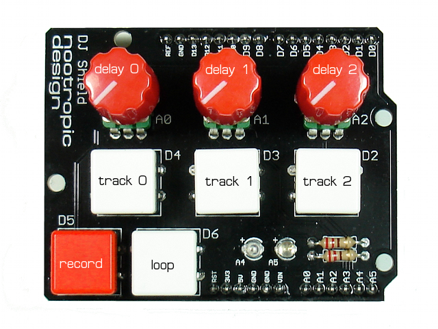
For this project, I used the DJ Shield because it provides all the buttons and pots.
You can build it on a breadboard if you want:
Record button = D5
Loop button = D6
Track 0 button = D4
Track 1 button = D3
Track 2 button = D2
Track 0 delay = A0
Track 1 delay = A1
Track 2 delay = A2
When the record button is tapped (pressed and released), it toggles the “passthrough” mode for the input. That is, when the sketch starts, the input is passed through to the output so you can hear it, but you can enable/disable the passthrough by tapping the record button.
To record a track, first enable the audio passthrough so you can hear the audio signal. Now press and hold the record button down, then hold down a track button to record the track. Release the track button when done recording, or if you exhaust the memory size for that track, the output will stop. To play the track (just once), press the track button. To cause the track to play in a loop, first press and hold the loop button, then press the track button. Now you can release the loop and track button, but the track will continue to play in a loop. Adjust the loop delay by adjusting the track’s potentiometer. To stop the looping of the track, tap the track button.
Now let’s record another track. Enable the input passthrough by tapping the record button. Now hold the record button and hold a new track button (like track 1) to record onto that track. Hold the loop button and tap the track button for your new track. Now tap the track button for the other track you recorded. They will both loop and will mix together. Go ahead and record a third track and loop them all together.
If the controls are confusing, just play with it for a while until you get the hang of it. You can enable debugging by uncommenting the line #define DEBUG and open the Arduino serial monitor with speed 115200. This will show you information about what is going on in the sketch.
Mixing Signals
Audio signals in this 8-bit project are represented as a series of 8-bit values in the range of [0,255]. Real audio signals are best described as waves that can have both positive and negative values, oscillating around a midpoint of zero. Audio signals mix together in an additive manner, where positive and negative values “cancel” each other out. Before we mix two signals together, first we normalize them so that the midpoint is 0 instead of 128. So 128 is subtracted from each value to give it a range of [-128,127] and we store the result in a signed integer. Now we add the values together to get the mixed signal.
It’s possible that two signals mixed together have exceed the maximum value of 127 or gone below the minimum value of -128. In this case we need to “clip” the value to the maximum or minimum. This will sound like distortion/noise when this happens. Read this for a better understanding of clipping.
After mixing signals together, we adjust the final value upward to the range of [0,255].
Performance Notes
In order to do all this mixing quickly, there are some compromises. The sample rate is 18 kHz and the samples are 8-bit audio.
The memory is divided up as follows: track 0 is on the first SRAM chip (128K) and can hold about 6 seconds. Tracks 1 and 2 split the second SRAM chip and are about 3 seconds each.
