This project is an introduction to the new nootropic design Audio Hacker shield. The first sketch you should use with the Audio Hacker is the 12-bit Sampler. Install the Audio Hacker Arduino library in your Arduino sketchbook, then choose the menu item File->Examples->Audio Hacker->Sampler_12bit.
Connect an audio source to the input jack of the Audio Hacker. For example, an MP3 player or computer with the volume at a high level. Make sure the bypass switch is in the left position (no bypass) and that the preamp gain potentiometer is set to the lowest level (counterclockwise). Connect the Audio Hacker output jack to amplified computer speakers, an input to a stereo receiver, or use headphones (but turn the Audio Hacker volume down first!).
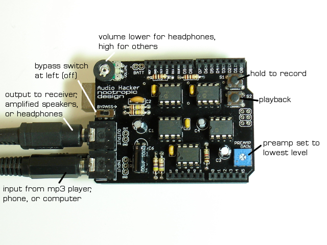
The audio input signal is sampled and reproduced on the output at 44.1 kHz. Everything you are hearing has been processed by the Arduino code. To compare it to the original signal, move the bypass switch to the right position. Now you are hearing the original signal (but after it has been summed to a mono signal). Can you hear a difference between the original and the audio sampled and reproduced by Arduino code?
With the bypass off (left position), press S1 to record the audio to memory (up to 8.6s) with a sample rate of 22 kHz. Press S2 to play it back.
Code
Sampling and playing audio requires precise timing. The Arduino timer1 is used to run an interrupt service routine (ISR) at a very specific frequency. The sample rate determines how often the interrupt service routine (ISR) is invoked. In order to efficiently store 12-bit audio samples, two samples are “packed” into 3 bytes before they are written to memory. To make this process efficient, read and write memory operations alternate. That is, we only write to memory on “odd” numbered ISRs and read from memory on “even” numbered ISRs.
8-bit Sampler
The 8-bit sampler File->Examples->Audio Hacker->Sampler_8bit is simpler code and can record longer samples. If you want to understand the Audio Hacker library API, this sketch will help you. Since this approach is simpler, we don’t trade off read and write operations on alternating ISRs. You will likely hear a sound quality difference, though. If you listen to samples with headphones you may hear background noise (like a hiss) in the samples compared to the 12-bit version.
Sample rate adjustments
You can make your own adjustments to the recording sample rate by changing the value of the variable recordingSampleRate. For example, set the value to 18000 for a sample length of 10.4 seconds. The lower the rate, the longer the sample you can record, but quality starts to suffer. See this table for information on sample lengths.
Adjustable playback rate
You can use a potentiometer connected to A0 to adust the playback rate of the recorded sample.
To enable this feature, make a minor code change to set adjustablePlaybackSpeed = true;. Arduino will prompt you to save your changed sketch to another location. Now connect a potentiometer to A0. If you are unsure how to wire it, see analog input tutorial. Then you can play back a sample with a different speed. Set the pot to midway point when you record, then adjust. Fun, huh?

Hi there.
I’m working on making my own audio hacker circuit following your instruction. However, there’s not a lot in the code that will compile. Any recommendations? Some things I can assume I myself change (like DEFAULT_RECORDING..) but what is UINT16_MAX – (F_CPU/passthroughSampleRate)? Please elaborate.
Apologies. Human error. I forget how to unzip folders at times :S
Im interested on using your board but as a sampling board for analoge signals, is it posible to save both input channels in RAM? i mean, not converting it into mono before saving.
Thx
The Audio Hacker only processes mono audio. An Arduino is not fast enough to process 2 channels.
Where can I buy a “Rugged Circuits” Flexible MIDI Shield?
Hello, i just installed the kit and i hear the mp3 from my laptop through headphones of the shield – but very very low levelled.
everything is soldered correctly. the 12-bit code example is transferred to the arduino.
turning both the gain and the volume knob does not make a change, although the bypass switch is on the left.
Can you maybe please help me?
The arduino app says the following:
In file included from /Users/Username/Documents/Arduino/libraries/audio-hacker-master/examples/Sampler_8bit/Sampler_8bit.ino:29:0:
/Users/Username/Documents/Arduino/libraries/audio-hacker-master/AudioHacker.h:32:0: warning: “UINT16_MAX” redefined
#define UINT16_MAX 65535
In file included from /Applications/Arduino.app/Contents/Java/hardware/tools/avr/lib/gcc/avr/7.3.0/include/stdint.h:9:0,
from /Applications/Arduino.app/Contents/Java/hardware/tools/avr/avr/include/inttypes.h:37,
from /Applications/Arduino.app/Contents/Java/hardware/tools/avr/avr/include/avr/pgmspace.h:88,
from /Applications/Arduino.app/Contents/Java/hardware/arduino/avr/cores/arduino/Arduino.h:28,
from sketch/Sampler_8bit.ino.cpp:1:
/Applications/Arduino.app/Contents/Java/hardware/tools/avr/avr/include/stdint.h:346:0: note: this is the location of the previous definition
#define UINT16_MAX (__CONCAT(INT16_MAX, U) * 2U + 1U)
That output from the compiler is just a warning. Are you sure the code was uploaded to the Arduino?
Are you using a 3.5mm stereo plug in the Audio Hacker input?
Is your audio output from computer loud enough? Plenty loud in bypass mode?
Thank you for the quick response.
It was definitely uploaded. i was using a mono modular patch cable plug in the audio hacker input. i thought for testing it should work. i turned both volume and gain down on the audio hacker, and put up the laptop volume as loud as possible without clipping. the bypass mode works normally. the board does not sample oder playback – i had other cables attached to the board, i will remove them and test again.
The mono plug is the problem. The jacks are stereo and the left and right channels are summed together. If you use a mono plug, the signal is being shorted directly to the ground sleeve. Only use stereo plugs.
Please tell me you didn’t record an audio demo using your camera’s microphone listening to speakers? How are we supposed to tell what the thing sounds like if it’s filtered by two additional reproduction steps, an air column, and a bunch of ambient noise?
Line in, line in!
Fair point, but I think was using my computer as output, and Audacity would not let me use it for input at the same time. It’s just a demo video. And this was 8 years ago.