Difficulty Level = 9 [What’s this?]
This was a fun project I built using a perf-board Arduino with GPS receiver, some LEDs, some long wire, some clever code, and a car!
I have this friend that has a speeding problem. So I built this device for my friend so he’ll know when he’s speeding. How will he know? Because when the small perf-board Arduino device with a GPS module detects that his vehicle’s speed is over the speed limit, it turns on a police lights display that is mounted on the inside of his car’s rear windshield. When he sees those flashing police lights in the rear-view mirror, he’ll know he needs to slow down!
OK, it’s me, but you already figured that out. If you weren’t smart, you wouldn’t be here. Here’s a rundown of this project’s features:- A simple perf-board Arduino circuit with an EM-406a GPS Receiver connected to the microcontroller
- A pair of CAT-5 cables running from the circuit to the back of my Honda Civic
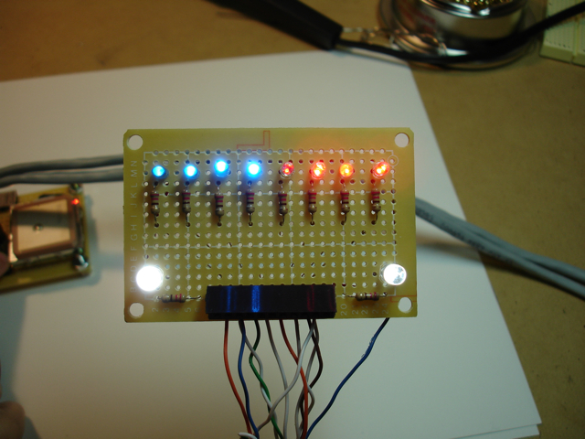
- A small perf-board with red and blue LEDs and two white LEDs representing the headlights of a police car. This small board is mounted on the inside of the rear windshield using suction cups.
- The software running on the microcontroller is programmed to know the speed limit in different locations near where I live and drive. I did this by specifying “speed zones” which are polygons and a speed limit. The polygons are defined as a list of latitude/longitude vertices.
- Whenever the GPS module reports the current position and speed (every second) the code determines which bounding polygon or “speed zone” the car is located in. If the GPS receiver reports that the current speed is greater than the speed zone’s limit, the police lights are activated. If below the speed limit, the lights will be turned off.
The Hardware
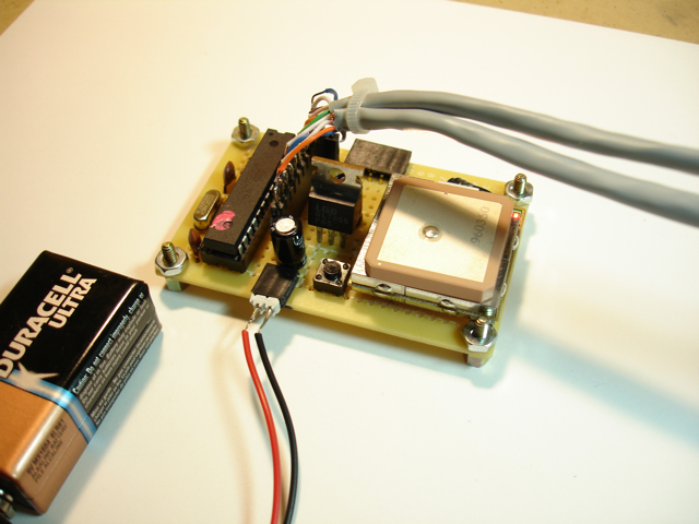
Look at this nice clean circuit…
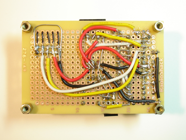
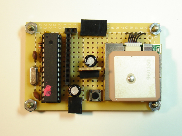 OMG don’t look at the bottom!
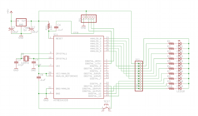
This is the schematic. This is just a perf-board version of an Arduino with a few extra things. Ten of the digital outputs are connected to a header for the cable to connect to. The GPS receiver is connected to power and ground, and tied to the TX and RX pins on the ATMEGA328 microcontroller. There is a test switch connected to Arduino pin 9 (ATMEGA328 pin 15). Lastly, there’s a 5 pin header for interfacing with a USB to serial board so I can program the chip. The 5 pins are 5V, GND, TX, RX, and the DTR signal for resetting the ATMEGA328 processor when the chip is programmed.
 Here’s the circuit board connected to the messy CAT-5 wiring harness. There’s about 6 feet of wire running to the LED circuit board.
The test button can be used to verify that everything is connected.
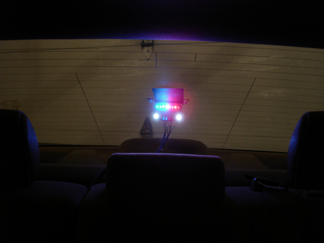
Here’s how the LED circuit board looks mounted in the rear windshield. I put a small square of black paper above the circuit board to reduce reflection on the glass.
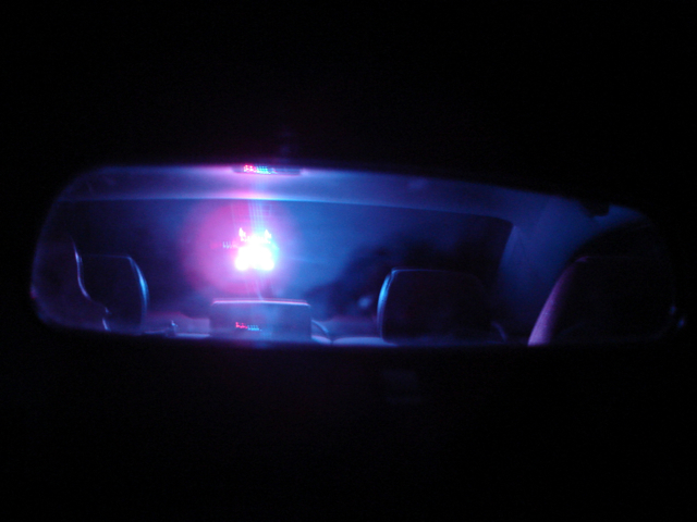
This is what it looks like when the police lights are activated. First a video shot to the rear of the car, then what it looks like in the rear view mirror. It was difficult to capture this on video, and it really doesn’t do it justice. I can tell you that when driving around at night, the illusion is fantastic. It really does look like there is a police car behind you!
The Code
Download the full Arduino code here.
The software running on the Arduino ATMEGA328 chip utilizes the wonderfully robust NewSoftSerial library for communicating with the EM-406a GPS module and the very convenient TinyGPS library for parsing the NMEA sentences from the EM-406a. Both of these awesome libraries are provided by Mikal Hart.
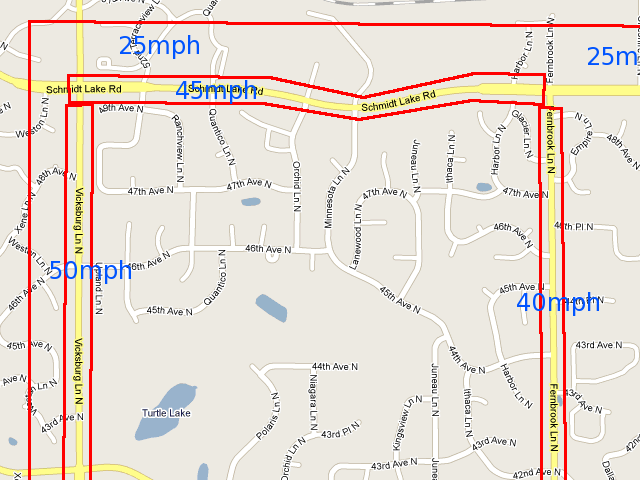
The TinyGPS library makes it easy to obtain the speed over ground in miles per hour. The method for determining whether my car is speeding or not depends not only on knowing how fast I’m going and where I am, but also knowing what the speed limit is where I am. For this, I have to hard-code in the information about various speed zones in the area I’m driving. This isn’t as tedious as it sounds. The idea is to define polygons on a map that represent different speed zones. Here’s a map I sketched in order to plan my code. I just did a screen capture in Google Maps and then drew on it with a simple drawing program. Click through for a larger version:
Then I used a simple tool provided at Google Maps called the “tile detector”. By clicking on the tile detector map you can easily determine the latitude and longitude of any point. Then I defined polygons in the setupSpeedZones(). Each zone has a speed limit and a list of vertices that define the polygon.
  // Rockford Road
  speedZones[0] = &SpeedZone(45);
  speedZones[0]->setVertices(6, (Vertex[6]){
      Vertex(45.027162772967756, -93.48137855529785),
      Vertex(45.02946790848425, -93.4742546081543),
      Vertex(45.02955889877115, -93.46193790435791),
      Vertex(45.02861865883124, -93.46172332763672),
      Vertex(45.02861865883124, -93.47412586212158),
      Vertex(45.02649547957147, -93.48133563995361)});


  // Schmidt Lake Rd
  speedZones[1] = &SpeedZone(45);
  speedZones[1]->setVertices(10, (Vertex[10]){
      Vertex(45.044176126280206, -93.48219394683838),
      Vertex(45.04390322470628, -93.47322463989258),
      Vertex(45.043387740403595, -93.46974849700928),
      Vertex(45.0440548368525, -93.46498489379883),
      Vertex(45.0440548368525, -93.46185207366943),
      Vertex(45.04332709488612, -93.46185207366943),
      Vertex(45.0433574176529, -93.46580028533936),
      Vertex(45.04272063617576, -93.46983432769775),
      Vertex(45.043266449304376, -93.47434043884277),
      Vertex(45.04332709488612, -93.48215103149414)});

      ...
The function getSpeedLimit() checks to see if the current GPS position is within each speed zone starting with the first one. Note that I defined a “catch all” speed zone with a limit of 25mph around the whole area. It’s ok if polygons overlap as long as you understand that the first match found will be the one that is used for the speed limit. This means you have to order your speed zone definitions with care. My catch all speed zone is defined last for this reason.
The algorithm for determining if a point is within a polygon is actually quite simple (I was surprised). I adapted my code from the algorithm provided here. I’m grateful that I found such a simple implementation to use.
The rest of the code should be pretty self-explanatory. If the car is speeding, turn on the police lights. If not, turn them off. Download the full Arduino code here.
Conclusions
This project worked amazingly well. The GPS receiver can take a long time (maybe 3 minutes) to get a fix when it is powered on, but once it gets a fix, it is very accurate. The only shortcoming is that the EM-406a receiver only outputs NMEA sentences once per second, so there’s a bit of lag, but for the most part this device would correctly react to speed limit changes almost immediately after crossing a speed zone polygon border.
The speed over ground reported by the EM-406a is pretty accurate but seemed to be about 2mph lower than what my speedometer in my car reports. So if I was in a 45mph speed zone, the police lights would not come on until I got up to about 47mph. If this difference is consistent, I could easily compensate for it in the software.
Overall, this was a really fun project with great results!

Cool idea! It’s quite possible your car speedometer is off by a few percent either from the factory or due to slight tire diameter differences versus new factory tires.
Except now when the cops are actually trying to pull him over he keeps going lol…. Awesome job. I might try this myself! My sister uses my car and pays more for insurance than me because of speeding.
It’s this illegal? Like, couldn’t you get nabbed for “impersonating a police officer” when the lights are on?
If I press the test button when the lights are on, then the lights go off. It’s just a tiny circuit board in the rear window pointing forward. It’s not large enough to look like I’m a police car.
Great project! Thanks for the write-up. Sorry about all the fake lawyers in the Hack-a-Day comments, though. Some people are no fun.
Worked great but my wife crashed the car trying to evade. Project still works though! I should send in pics. Funeral is Tuesday. JK ;)
I am trying to make this work on my arduino but I’m not sure how or where to load the TinyGPS and NewSoftSerial . I tried pasteing your code directly to my arduino IDE version 0018 and It comes up with errors. What do I need to do to get mine working. I am usung a regular arduino with a prallax gps attached and the led output is only one pin on the arduino board. Any help would be GREATLY appreciated. Thank you.
Did you install NewSoftSerial and TinyGPS in your sketchbook libraries folder?
Ok, I’m sorry if I am not up to speed. I figured out how to load TinyGPS etc. and by downloading to my Arduino with the GPS disconnected I got the program to load with no errors. Then I installed(plugged in) my GPS. I would like to turn on only one LED when I’m speeding though. I don’t need the lights to blink or anything. I was thinking about eliminating the red and blue and one of the headlights. I just want one light on when speeding and off when not. Also i do not need a test button. I would really appreciate help in knowing which parts of the code I need to remove or change. THANK YOU SO MUCH!
Spencer, if you want to write code for a project you want to accomplish, then — how do I say this nicely — you’ll have to figure out how to write the code. If you’ve ever done any coding, you should have no problem modifying the code to accomplish what you want. If you are inexperienced in writing code, then you’ve got some learning to do. You can do it if you try. But you have to *try*. You should not expect someone else to tell you what code to change. It’s your project, right? For a bit more on this subject, please read this thoughtfully: http://nootropicdesign.com/projectlab/difficulty-levels/
Then read it again!
This is a great project. I’m just starting to work on a similar project. I want to design a system for a gps guided tour of my college campus. I found your project and i’ve been working with the code but i’m having some trouble. I’m still just testing out your code so I’ve just set up zones where i live and set the speed to 1 and tried that but i’m getting some weird readings (I will be sitting still and it will say i’m in zones miles away). I was hoping you could answer a few questions.
1)does it matter which way you define the polygons? I’ve been going in a clockwise direction. and i’m only using 4 sided polygons currently.
2) Did you have problems when outside of your catch-all zone or without it. If i remove the catch-all and just define several individual sites then it believes i’m in all of of the zones.
3) is their a size limit to the polygons? I have tried the exclusion zone around my campus and also around my whole county
I’ve removed the button code and i’ve removed the code for flashing the lights and set only headlight1 to activate with a digitalWrite but i haven’t modded any other parts of the code except to add serial out for my own debugging and some delays so the ide doesn’t freeze up when i’m watching. Would it be ok if i sent you the code that i have now?
Hi. I think with some careful debugging you’ll be able to figure out what’s wrong. To answer your questions:
1) no, I don’t think clockwise or counterclockwise matters. I think I defined mine clockwise.
2) I don’t think I had any problems when not in a polygon. If it believes you are in all the zones, then double check your logic or add some debugging. I had to do a lot of debugging. Print data to Serial out to really figure out why your input would be matching all of them.
3) Size doesn’t matter. The code doesn’t know if the units are degrees or miles or light years.
In short, just stick with it. You’ll find a logic problem I think. If you want, you can send me your code and I will have a look. michael at nootropicdesign dot com
great home project. Very cool with the police lights. lots of work in doing a limited speed area. I am looking for a gps off the self that does similar with voice warning/flashing. I think tomtom does the same, but may be limited to only major highways.
Great Project,
Just want to let you know your link for Google tile detector no longer works. Google changed to maps API V2. Do you know the right tool to use now?
Thank you,
J.C. Woltz
J.C., thanks for letting me know that the Google tile detector link was bad. I have updated it. I just googled for “google maps tile detector”.
That is freakin sweet!!!!!!!!!!!!!!!!!!!!!!!!!!!!!!!!!!!!!!!!!!!!
Can you tell me the total cost??
WOW GREAT PROJECT AND GREAT PAGE THANKS FOR YOUR KNOWLEDGE CONGRATULATIONS!!! :)
hey,so how was its flow chart,do you mind showin it up
This is such a clever, fun, and useful project. I LOL’d several times.
So, I’m a total newbie, here are my questions:
– Did you custom build that entire “simple perf-board Arduino circuit”?
– If so, can you point me to a good tutorial to replicate your work there?
– Also if so, what are the advantages/disadvantages of doing it that way versus starting with a “stock” Arduino circuit like the Arduino Uno — http://arduino.cc/en/Main/ArduinoBoardUno?
Thanks!
Yes, I built a simple perf-board based Arduino. Just google it, there are many resources for doing this.
The advantage of building your own circuit are that you don’t have to use a $30 board in a project. Sometimes you want a smaller solution instead of using a full Arduino.
Hi Michael, nice project. I want to use this system for my car, but instead of showing output with LED, I want to use G.S.M shield to send the location and speed to my HP (Hand Phone). can you guide me in it.
In Arduino examples, there is coding that can be used to send S.M.S to HP but I’m not sure how can mix together. that’s few line codes, can you please help me !?(please mail me if possible)
Warm regard.
nice bro…I love your project…
does anybody had some issue like , no matching function for call to ‘Vertex::Vertex(int)’ ?
Arduino: 1.8.4 (Windows 7), Board: “Arduino/Genuino Uno”
In function ‘void setupSpeedZones()’:
sketch_feb19a:102: error: taking address of temporary array
});
^
sketch_feb19a:119: error: taking address of temporary array
});
^
exit status 1
taking address of temporary array
does anybody here know how i can fix this part? thank you!
try the arduino version below 2010
Hi michael thx for ur tutorial but i cant find the algorithm plz can u help me :)))
The link to the source code is right in the article: source code
sorry to disturb you but is it possible that you explain to me the function getSpeedLimit() ^^
I provided all the source code. I don’t know what there is to explain. Each zone has a speed limit.
can u please let me know, which version of Arduino IDE you have used??
Use Ardunio 0019
Guys, use the Ardunio 0019 version to make this work.
hi there
nice work>>> can we purchase this board >>