Difficulty Level = 8 [What’s this?]
UPDATE: Check out the new robotics platform project!
I built a wireless robotics platform from a cheap R/C car, an Arduino with XBee shield, small microswitch sensors, and a Processing program running on a remote computer to control the vehicle. The vehicle is completely controlled by the code running on the remote computer which allows very rapid prototyping of the code to tell the vehicle what to do and how to react to the sensor events received from the vehicle. I’m hoping this is a good way to teach my 9-year old son about programming.
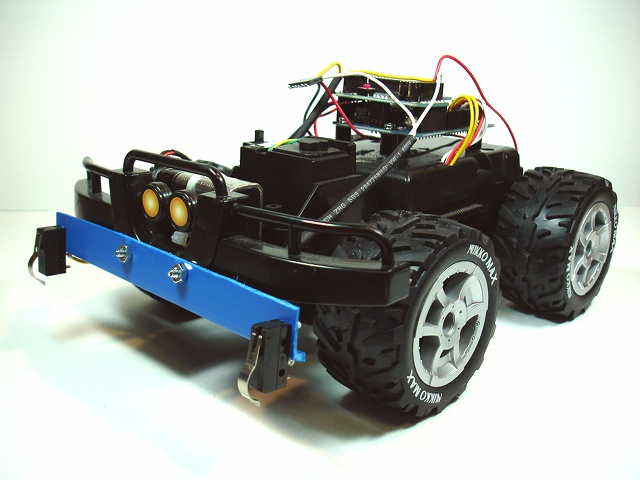
Wireless computer-controlled robotics platform built on cheap RC vehicle, Arduino microcontroller, and XBee radios
- All logic controlling the vehicle is performed in a Processing program running on remote computer. The Arduino program listens for commands from the remote computer.
- Bi-directional wireless communication over XBee radios with (theoretical) 1-mile range. I’ve accomplished 1/4 mile range with these radios.
- Sensor events are transmitted from the vehicle to the controlling computer. This vehicle has 3 microswitches – two on front bumper and one at the rear.
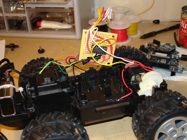
- Original circuitry of vehicle replaced with dual H-Bridge circuit to control drive motor and turn motor. Drive motor is controlled with variable speed.
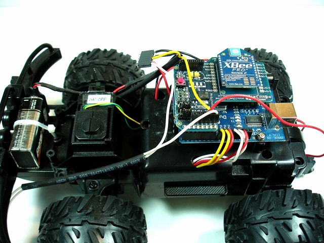
- Power: Vehicle motors powered by 4 AA batteries. Arduino with XBee shield powered by 9V battery mounted at front of vehicle.
- Simple communications protocol: 2 byte commands from controller to vehicle, one byte sensor readings from vehicle to controller.
The Hardware
There’s nothing special about the configuration of the XBee radios. They are running the AT firmware (“transparent mode”) which allows them to simply exchange serial data. The Libelium XBee shield on top of the Arduino makes it easy to read/write serial data from Arduino code.
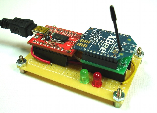
The controller computer connects to an XBee radio via a Sparkfun FTDI USB breakout board. This is just a simple perf-board circuit connecting the USB interface to the XBee. It’s as simple as connecting the RX/TX pairs together, and giving it power.
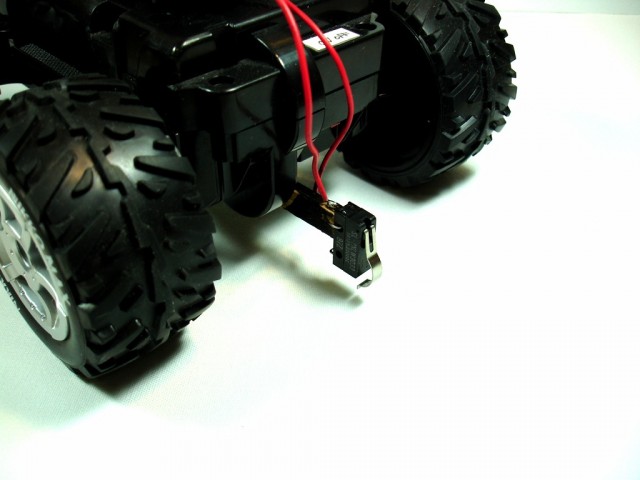
Here’s a view of a microswitch collision sensor on the back of the vehicle. It’s mounted on a small piece of wood (yes, wood) glued to the chassis.
The Code
This is a listing of the Arduino code. It is fairly simple and self-explanatory because the Arduino just listens for commands and sends sensor readings. A BEGIN_COMMAND delimiter indicates that the next two bytes are a command. The first byte of a command is a bit pattern telling the Arduino whether to go forward, backward, turn left, or turn right. There is one bit assigned to each of those 4 directions (4 bits are unused and reserved for future functions). The second byte represents speed. By using PWM on the H-bridge enable pin, the speed of the vehicle can be controlled.
If a sensor switch is closed, then a byte with the appropriate bit is sent back to the controlling computer. There is logic to debounce the switches. Studying this code is left as an exercise for the reader. Feel free to download the Arduino sketch.
// Pin assignments
#define LEFT_PIN 13         // red/black
#define TURN_ENABLE_PIN 12  // white
#define DRIVE_ENABLE_PIN 11 // white/black
#define RIGHT_PIN 10        // red
#define BACKWARD_PIN 9      // yellow/black
#define FORWARD_PIN 8       // yellow

#define LEFT_FRONT_BUMPER_PIN 7     // white
#define RIGHT_FRONT_BUMPER_PIN 6    // yellow
#define REAR_BUMPER_PIN 5           // red

// Input Commands
#define BEGIN_COMMAND 0x7F
#define FORWARD 0x1
#define BACKWARD 0x2
#define LEFT 0x4
#define RIGHT 0x8

// Sensor Data
#define LEFT_FRONT_BUMPER 0x1
#define RIGHT_FRONT_BUMPER 0x2
#define REAR_BUMPER 0x4
#define DEBOUNCE_THRESHOLD 50


int sensorData = 0;
int lastSensorData = 0;
int lastLeftFrontBumperReading;
int lastRightFrontBumperReading;
int lastRearBumperReading;
int leftFrontBumperReadingTime;
int rightFrontBumperReadingTime;
int rearBumperReadingTime;
int command[2];

void setup() {
  Serial.begin(9600);

  pinMode(DRIVE_ENABLE_PIN, OUTPUT);
  pinMode(TURN_ENABLE_PIN, OUTPUT);
  pinMode(LEFT_PIN, OUTPUT);
  pinMode(RIGHT_PIN, OUTPUT);
  pinMode(BACKWARD_PIN, OUTPUT);
  pinMode(FORWARD_PIN, OUTPUT);

  pinMode(LEFT_FRONT_BUMPER_PIN, INPUT);
  digitalWrite(LEFT_FRONT_BUMPER_PIN, HIGH);
  pinMode(RIGHT_FRONT_BUMPER_PIN, INPUT);
  digitalWrite(RIGHT_FRONT_BUMPER_PIN, HIGH);
  pinMode(REAR_BUMPER_PIN, INPUT);
  digitalWrite(REAR_BUMPER_PIN, HIGH);

}

void loop() {

  // Read sensors and transmit
  readSensors();
  if (sensorData != lastSensorData) {
    Serial.write(sensorData);
    lastSensorData = sensorData;
  }


  // listen for wireless commands
  if (Serial.available() > 0) {
    if (readCommand() > 0) {
      executeCommand();
    }
  }
}


void readSensors() {
  int s;

  s = digitalRead(LEFT_FRONT_BUMPER_PIN);
  if (s != lastLeftFrontBumperReading) {
    leftFrontBumperReadingTime = millis();
  }
  if ((millis() - leftFrontBumperReadingTime) > DEBOUNCE_THRESHOLD) {
    if (s == LOW) {
      sensorData |= LEFT_FRONT_BUMPER;
    } else {
      sensorData &= ~LEFT_FRONT_BUMPER;
    }
  }
  lastLeftFrontBumperReading = s;

  s = digitalRead(RIGHT_FRONT_BUMPER_PIN);
  if (s != lastRightFrontBumperReading) {
    rightFrontBumperReadingTime = millis();
  }
  if ((millis() - rightFrontBumperReadingTime) > DEBOUNCE_THRESHOLD) {
    if (s == LOW) {
      sensorData |= RIGHT_FRONT_BUMPER;
    } else {
      sensorData &= ~RIGHT_FRONT_BUMPER;
    }
  }
  lastRightFrontBumperReading = s;

  s = digitalRead(REAR_BUMPER_PIN);
  if (s != lastRearBumperReading) {
    rearBumperReadingTime = millis();
  }
  if ((millis() - rearBumperReadingTime) > DEBOUNCE_THRESHOLD) {
    if (s == LOW) {
      sensorData |= REAR_BUMPER;
    } else {
      sensorData &= ~REAR_BUMPER;
    }
  }
  lastRearBumperReading = s;
}

int readCommand() {
  int b = Serial.read();
  if (b == BEGIN_COMMAND) {
    command[0] = readByte();
    command[1] = readByte();
    return 1;
  } else {
    return 0;
  }
}

// blocking read
int readByte() {
  while (true) {
    if (Serial.available() > 0) {
      return Serial.read();
    }
  }
}

void executeCommand() {
  int c = command[0];
  int speed = command[1];

  digitalWrite(DRIVE_ENABLE_PIN, LOW);
  if (c & FORWARD) {
    digitalWrite(BACKWARD_PIN, LOW);
    digitalWrite(FORWARD_PIN, HIGH);
  }
  if (c & BACKWARD) {
    digitalWrite(FORWARD_PIN, LOW);
    digitalWrite(BACKWARD_PIN, HIGH);
  }
  if (c & (FORWARD | BACKWARD)) {
    analogWrite(DRIVE_ENABLE_PIN, speed);
  }

  digitalWrite(TURN_ENABLE_PIN, LOW);
  if (c & LEFT) {
    digitalWrite(RIGHT_PIN, LOW);
    digitalWrite(LEFT_PIN, HIGH);
  }
  if (c & RIGHT) {
    digitalWrite(LEFT_PIN, LOW);
    digitalWrite(RIGHT_PIN, HIGH);
  }
  if (c & (LEFT | RIGHT)) {
    digitalWrite(TURN_ENABLE_PIN, HIGH);
  }
}
Now let’s look at the Processing code that really controls the vehicle from afar. I used Procesing because it’s easy for beginners, has an IDE that is familiar to Arduino coders, and hides a lot of complexity. And I’ve been coding in Java since last century — Processing is just Java simplified, so it’s second-nature for me.
This Processing sketch doesn’t actually have a visual interface at all. It just communicates with the transmitter via the USB serial interface. Before I show the entire Processing sketch, I just want to show you the part of the code you write in the draw() method that controls the vehicle. The draw() method is the same concept as the loop() method in Arduino. This is how you tell the vehicle what to do:
void draw() {

   ...

  speed = 9;  // set speed value.  Valid values are 0-9.
  forward(1000);  // go forward for 1000ms (one second)
  stop();
  right();  // turn wheels
  backward(500);  // backward for half a second
  left();
  speed = 5;
  backward(500);
  stop();
  forward(2000);
  //  you get the idea...

  straight();  // wheels straight
  end();  // end the program.  Without this, it repeats.
}
What about sensor events that we receive from the vehicle? We handle those by writing methods for each event. These methods will be called as soon as the sensor reading is received. The currently running program (like above) will be terminated immediately and the appropriate method below will run. It looks like we’re only checking for collision events at the beginning of the draw() method, but when an event happens, the program instructions stop and we come back to the beginning of the draw() immediately so we can handle the event. Here’s the full draw() method and the event handling methods:
void draw() {

  if (rightFrontBumper) {
    println(timestamp() + " ----RIGHT FRONT IMPACT!----");
    rightFrontBumper();
  }
  if (leftFrontBumper) {
    println(timestamp() + " ----LEFT FRONT IMPACT!-----");
    leftFrontBumper();
  }
  if (rearBumper) {
    println(timestamp() + "-------REAR IMPACT!--------");
    rearBumper();
  }

  speed = 9;  // set speed value.  Valid values are 0-9.
  forward(1000);  // go forward for 1000ms (one second)
  stop();
  right();  // turn wheels
  backward(500);
  left();
  speed = 5;
  backward(500);
  stop();
  forward(2000);
  //  you get the idea...

  straight();  // wheels straight
  end();  // end the program.  Without this, it repeats.
}

void leftFrontBumper() {
  leftFrontBumper = false;
  running = true;
  left();
  speed = 9;
  backward(800);
  straight();
  end();
}

void rightFrontBumper() {
  rightFrontBumper = false;
  running = true;
  right();
  speed = 9;
  backward(800);
  straight();
  end();
}

void rearBumper() {
  rearBumper = false;
  running = true;
  right();
  speed = 9;
  forward(1000);
  straight();
  end();
}
You can start your program again by pressing the ‘s’ key. Also, after a program is done running, you can control the vehicle with the arrow keys. For example, if you want to position the vehicle for another run.
The whole idea here is that this provides a platform for programming the vehicle to do whatever you wish, and dealing with collisions however you want. There’s a lot of potential here for more sensors and more commands to the vehicle (How about a robotic arm? Infrared sensors?).
There’s a lot more code in the Processing sketch that handles the communication, etc. Here is an entire listing with simple code for the program to run, and simple event handling methods for collisions. I won’t explain every bit of the code, but if you like code, you’ll be able to understand it. Feel free to download the entire Processing sketch that implements the remote vehicle controller.
import processing.serial.*;

Serial port = null;
String portName;
int lastInput = 0;
int[] command = new int[2];
int[] lastCommand = new int[2];
int speed = 9;
int lastSpeed = 0;
int speedStep = (255 - 130) / 8;
boolean running = true;
boolean leftFrontBumper = false;
boolean rightFrontBumper = false;
boolean rearBumper = false;

int DIR_FORWARD = 0x1;
int DIR_BACKWARD = 0x2;
int DIR_LEFT = 0x4;
int DIR_RIGHT = 0x8;
int BEGIN_COMMAND = 0x7F;

// Sensor Data
int LEFT_FRONT_BUMPER = 0x1;
int RIGHT_FRONT_BUMPER = 0x2;
int REAR_BUMPER = 0x4;

SimpleDateFormat df = new SimpleDateFormat("hh:mm:ss.SSS");

void setup() {
  size(1, 1);

  portName = Serial.list()[0];
  try {
    port = new Serial(this, portName, 9600);
  } catch (Exception e) {
    e.printStackTrace();
  }
}

String timestamp() {
  return df.format(new Date());
}

void draw() {

  if (rightFrontBumper) {
    println(timestamp() + " ----RIGHT FRONT IMPACT!----");
    rightFrontBumper();
  }
  if (leftFrontBumper) {
    println(timestamp() + " ----LEFT FRONT IMPACT!-----");
    leftFrontBumper();
  }
  if (rearBumper) {
    println(timestamp() + " -------REAR IMPACT!--------");
    rearBumper();
  }

  speed = 9;
  left();
  forward(1200);
  right();
  forward(800);
  stop();

  left();
  backward(1200);
  stop();
  right();

  forward(2500);
  stop();

  left();
  backward(4000);

  end();
}

void leftFrontBumper() {
  leftFrontBumper = false;
  running = true;

  left();
  speed = 9;
  backward(800);
  straight();
  end();
}

void rightFrontBumper() {
  rightFrontBumper = false;
  running = true;

  right();
  speed = 9;
  backward(800);
  straight();
  end();
}
void rearBumper() {
  rearBumper = false;
  running = true;

  speed = 9;
  forward(1000);
  straight();
  end();
}


void end() {
  if (!running) return;
  stop();
  straight();
  println(timestamp() + " -----------END------------");
  println("Press 's' to restart program or use arrow keys to control vehicle.");
  running = false;
}

void interruptibleDelay(int millis) {
  int start = millis();
  int d;
  while (running) {
    int timeLeftToWait = millis-(millis()-start);
    d = min(10, timeLeftToWait);
    if (d <= 0) return;
    delay(d);
  }
}


void forward(int millis) {
  if (!running) return;
  forward();
  interruptibleDelay(millis);
  stop();
}

void forward() {
  if (!running) return;
  doForward();
}

void doForward() {
  command[0] = command[0] & ~DIR_BACKWARD;
  command[0] = command[0] | DIR_FORWARD;
  sendCommand();
}

void backward(int millis) {
  if (!running) return;
  doBackward();
  interruptibleDelay(millis);
  stop();
}

void backward() {
  if (!running) return;
  doBackward();
}

void doBackward() {
  command[0] = command[0] & ~DIR_FORWARD;
  command[0] = command[0] | DIR_BACKWARD;
  sendCommand();
}

void left() {
  if (!running) return;
  doLeft();
}

void doLeft() {
  command[0] = command[0] & ~DIR_RIGHT;
  command[0] = command[0] | DIR_LEFT;
  sendCommand();
}

void right() {
  if (!running) return;
  doRight();
}

void doRight() {
  command[0] = command[0] & ~DIR_LEFT;
  command[0] = command[0] | DIR_RIGHT;
  sendCommand();
}

void straight() {
  if (!running) return;
  doStraight();
}

void doStraight() {
  command[0] = command[0] & ~DIR_RIGHT;
  command[0] = command[0] & ~DIR_LEFT;
  sendCommand();
}

void stop() {
  if (!running) return;
  doStop();
}
void doStop() {
  command[0] = command[0] & ~DIR_BACKWARD;
  command[0] = command[0] & ~DIR_FORWARD;
  sendCommand();
}


void serialEvent(Serial p) {
  int input = p.read();
  lastInput = input;
  processInput(input);
}


void processInput(int input) {
  if ((input & LEFT_FRONT_BUMPER) != 0) {
    stop();
    leftFrontBumper = true;
    running = false;
  }

  if ((input & RIGHT_FRONT_BUMPER) != 0) {
    stop();
    rightFrontBumper = true;
    running = false;
  }

  if ((input & REAR_BUMPER) != 0) {
    stop();
    rearBumper = true;
    running = false;
  }
}


void sendCommand() {
  if (!isNewCommand()) {
    return;
  }
  if (port != null) {
    port.write(BEGIN_COMMAND);
    port.write(command[0]);
    command[1] = 255 - ((9 - speed) * speedStep);
    port.write(command[1]);
    if ((command[0] & DIR_FORWARD) > 0) {
      print(timestamp() + " FORWARD\t");
    }
    if ((command[0] & DIR_BACKWARD) > 0) {
      print(timestamp() + " BACKWARD\t");
    }
    if (((command[0] & DIR_FORWARD) == 0) && ((command[0] & DIR_BACKWARD) == 0)) {
      print(timestamp() + " STOP\t");
    }
    if ((command[0] & DIR_LEFT) > 0) {
      print("LEFT\t");
    }
    if ((command[0] & DIR_RIGHT) > 0) {
      print("RIGHT\t");
    }
    if (((command[0] & DIR_LEFT) == 0) && ((command[0] & DIR_RIGHT) == 0)) {
      print("STRAIGHT\t");
    }
    println("SPEED=" + speed);


    lastCommand[0] = command[0];
    lastCommand[1] = command[1];
    lastSpeed = speed;
  }
}

boolean isNewCommand() {
  return ((command[0] != lastCommand[0]) || (command[1] != lastCommand[1]) || (speed != lastSpeed));
}

void keyPressed() {
  if (key == CODED) {
    if (keyCode == UP) {
      doForward();
    }
    if (keyCode == DOWN) {
      doBackward();
    }
    if (keyCode == LEFT) {
      doLeft();
    }
    if (keyCode == RIGHT) {
      doRight();
    }
  }
  if ((key >= '1') && (key <= '9')) {
    speed = 9 - ('9' - key);
    println("set speed = " + speed);
  }
  if (key == 's') {
    running = true;
  }
}

void keyReleased() {
  if (key == CODED) {
    if (keyCode == UP) {
      doStop();
    }
    if (keyCode == DOWN) {
      doStop();
    }
    if (keyCode == LEFT) {
      doStraight();
    }
    if (keyCode == RIGHT) {
      doStraight();
    }
  }
}
Demo
Here's a demo where I tried to program the vehicle to negotiate an obstacle course. This is the instructions and the sensor event handling code:
void draw() {

  if (rightFrontBumper) {
    println(timestamp() + " ----RIGHT FRONT IMPACT!----");
    rightFrontBumper();
  }
  if (leftFrontBumper) {
    println(timestamp() + " ----LEFT FRONT IMPACT!-----");
    leftFrontBumper();
  }
  if (rearBumper) {
    println(timestamp() + " -------REAR IMPACT!--------");
    rearBumper();
  }

  speed = 9;
  left();
  forward(1200);
  right();
  forward(800);
  stop();

  left();
  backward(1200);
  stop();
  right();

  forward(2500);
  stop();

  left();
  backward(4000);

  end();
}

void leftFrontBumper() {
  leftFrontBumper = false;
  running = true;

  left();
  speed = 9;
  backward(800);
  straight();
  end();
}

void rightFrontBumper() {
  rightFrontBumper = false;
  running = true;

  right();
  speed = 9;
  backward(800);
  straight();
  end();
}

void rearBumper() {
  rearBumper = false;
  running = true;

  speed = 9;
  forward(1000);
  straight();
  end();
}
Let's see how well it worked. I tried to navigate through the cones without hitting them. The wheels skidded a bit when changing direction on the smooth floor. At the end, I purposefully ran into something backwards to demonstrate a sensor event. See if you can match up the vehicle's actions with the code above.
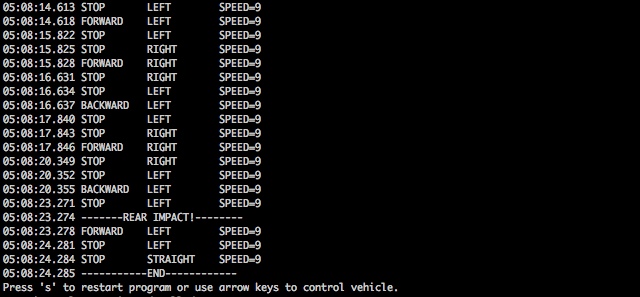
Finally, here's a screenshot of the Processing console that shows everything that happened. Notice the rear impact event at the end.
 Hope you enjoyed reading about this project. It was a lot of work and I hope that it can be the basis for future robotics experimentation.
Hi Michael,
I saw this featured on hackaday and noticed it was very similar to my capstone engineering project (to be completed april 7th). We’re controlling an RC car through a zigbee mesh network using XBees and the MIT Handyboard on the car.
Did you have any issues with lost control packets being retransmitted causing odd behaviour? When our vehicle left the mesh and then returned, it would drive off for a little while. We assumed this was due to the packets being left in the network to be retransmitted when the node came back in, but couldn’t find any settings to disable retransmission on the XBee series 2 (not pros).
Peter
Peter,
No, I’ve never had any problems with lost packets and such using XBees. But I only have 2 so I’m not really building a mesh or anything complex. I’ve had reliable communication at 1/4 mile using these radios. The published (theoretical) range is 1 mile for the models I have.
Looks like a great start indeed! Very cool to have the wireless thing working. I’m in the middle of getting bluetooth comm set up for my main robot. There’s definitely a fair bit of tinkering involved. :) Looking forward to updates. –Michael
Thanks Michael, probably has to do with lost packets like we suspected then.
can you send me an email of the electronics partsbreakdown so i can purchase the parts needed. i have an rc carthat i can use but i need to know what hardware and where to get it.
Kevin, well I don’t have your email address. But here’s the parts list:
Arduino
Libelium XBee shield
Two XBee radios (I used Series 2)
Sparkfun FTDI USB to serial breakout board (BOB-00718)
XBee breakout board (Sparkfun BOB-08276)
2mm female headers for XBee breakout board (Sparkfun PRT-08272)
male headers for XBee breakout board and FTDI breakout board.
SN754410 Quad Half H-Bridge chip (Sparkfun COM-00315)
3 small microswitches
wire
I think that’s about it.
Hey Michael,
Did you you ever think of going public with the wireless robots? They’re awesome. I think they will be much more popular once WiMax kicks in. That’s the next big thing in wireless communications. I guess it’s up to the telecom towers manufacturers now.
Michael,
First off all – great project! I hope to recreate it this summer with my kids. Can you say – where did purchased Libelium XBee shield and XBee radios?
I bought the XBee shield from Adafruit, I think. And I bought the XBee radios from Sparkfun.
Hi Michael,
Contratulations with your project! It looks very tidy! I was doing a similar project but there’s one thing I don’t understand well. It’s about the control of the steering motor. I am using the original PCB of the toy car, from which I removed the RX2B chip. I use PWM signals generated from my Arduino to feed into the H-bridge on the original PCB.
Can you show the part in your code where you control the steering, also the part with the speed value declaration? I’ve just blown a transistor and I think it was due to the fact that I made my left pin go high without making my right pin go low…
Thanks in advance!
The full Arduino code is in the post, and is downloadable. Steering is controlled just by writing to the correct pins. First disable the turning, then set the right and left pins correctly before enabling the turning on the H-Bridge.
digitalWrite(TURN_ENABLE_PIN, LOW);
if (c & LEFT) {
digitalWrite(RIGHT_PIN, LOW);
digitalWrite(LEFT_PIN, HIGH);
}
if (c & RIGHT) {
digitalWrite(LEFT_PIN, LOW);
digitalWrite(RIGHT_PIN, HIGH);
}
if (c & (LEFT | RIGHT)) {
digitalWrite(TURN_ENABLE_PIN, HIGH);
}
Its great. I tried designing it using ASK for the communication part, but it introduced some noise. So would you mind showing me the circuit
Hi, Thanks for documenting your project. I’m considering a similar RC car for a router bot and have few questions for you if you may.
On the hackaday I read that the RC platform you used was a Nikko 1:19 scale model. Do you know what is the stall current of the dc motors on these cars? Looking at the spec sheet of the H-bridge chip that you used the maximum current output seems to be 1A. This seems to be fairly low. I’m concerned with the added weight of the router motors won’t provide enough torque.
@Dhruba: The circuit is very simple — just hook up the two motors to an L293D or SN754410 H-Bridge according to the datasheet. Have a look at the H-Bridge datasheet and you’ll have no problem hooking two motors to it. The Arduino code clearly explains which pins are connected to the H-Bridge.
@sj: You raise a good question. I don’t know how much current is pulled by the motors when they are stalled. (I think that’s what you are asking). If you are concerned, I think there are power h-bridges available. Or you might be able to build your own with MOSFETs.
Hi Micheal,
Thanks for publishing your work. I’m fresh out from university, an am planning to build a similoar robotics platform, just a few things:
1- Would you recommend using “Arduino Compatible 4 Wheel Drive Mobile Robot Platform” over yours (i.e. radio control 1:10 car)? The prices are kinda similar, but I’m not sure which one to buy!
here’s the link if you wanna have a look.
http://cgi.ebay.co.uk/Arduino-Compatible-4-Wheel-Drive-Mobile-Robot-Platform-/140452311609?pt=UK_ToysGames_RadioControlled_JN&hash=item20b39c3239#ht_2141wt_1137
2- It still amazes me how that tiny H-bridge handles current supply (your car in the video was agile enough I would say!). Considering it even gives each motor maximum of 1A, still it’s fairly nothing, I’m sure these brushed motors can devour much more current (6 to 10A I guess). I was considering higher amp demand for the motors, but your car seems doing just fine with that little power supply, saving the world’s energy sources :) .
Cheers,
Just found another retailer with full de-assembled parts of the Arduino Robotic Platform:
http://www.robotshop.com/dfrobot-4wd-arduino-mobile-platform-3.html
Yes, I saw that robotics platform a while back and I think it would work great. Looks cool. Maker Shed has it for $50:
http://www.makershed.com/ProductDetails.asp?ProductCode=MKSEEED8
I like the two-wheel version better. I think it would be more agile.
http://www.makershed.com/ProductDetails.asp?ProductCode=MKSEEED7
You could be right about the current draw of the motors. I didn’t measure it and I could be exceeding the limits of the H-Bridge.
I would still prefer the 4 wheel platform, cause it allows doing stuff like this:
http://www.youtube.com/watch?v=kmnYl479Ets
What do you think?
Hi, I thought I should follow up my question regarding the current draw of the DC motors as I’m currently dissembling the exact same model RC car.
The motor can draw in excess of 3A when stalled. However on a smooth surface (such as desk or wooden floor) the motor can drive the car while drawing 0.5A on 50% PWM duty without any problems. I believe the current draw is low due to the gearing. Even though there are no indications as to the make or model of the motor my guess is its Mabuchi RS-540SH or similar.
@sj, thanks for the follow-up. Back when I did this project, I wasn’t thinking much about the current draw of the motors relative to what the H-bridge could deliver.
Nice!
I shown this to my kid and my kid would like to “donate” back his Nikko R/C for me to implement Arduino on his old toy. My question for you is, do you have the picture of what wire diagram of the wires from the R/C toy and their connections to Arduino ?
Much appreciated !
Duncan
Here’s the link from Purdue
http://web.ics.purdue.edu/~fwinkler/616/sn754410_Arduino.pdf
I noticed that on the processing code it says
//
import processing.serial.*;
Serial port = null;//Whats do we put for the port or should I leave it.
String portName;
//then adding on to that it says this
if (port != null) {//—right here it says if the port is null so all it does is spam the monitor
port.write(BEGIN_COMMAND);
port.write(command[0]);
command[1] = 255 – ((9 – speed) * speedStep);
port.write(command[1]);
if ((command[0] & DIR_FORWARD) > 0) {
print(timestamp() + ” FORWARD\t”);
}
if ((command[0] & DIR_BACKWARD) > 0) {
print(timestamp() + ” BACKWARD\t”);
}
if (((command[0] & DIR_FORWARD) == 0) && ((command[0] & DIR_BACKWARD) == 0)) {
print(timestamp() + ” STOP\t”);
}
if ((command[0] & DIR_LEFT) > 0) {
print(“LEFT\t”);
}
if ((command[0] & DIR_RIGHT) > 0) {
print(“RIGHT\t”);
}
if (((command[0] & DIR_LEFT) == 0) && ((command[0] & DIR_RIGHT) == 0)) {
print(“STRAIGHT\t”);
}
println(“SPEED=” + speed);
lastCommand[0] = command[0];
lastCommand[1] = command[1];
lastSpeed = speed;
}
}
The port variable is initialized in the setup() method.
The code:
if (port != null) {
means “if the port is NOT null”. It doesn’t mean “if the port is null”.
Hello Michael,
Are there any settings for the two xbes’s?
How they would see each other to communicate?
Good remote controlis the blast in recent times. I’m always in need of mobility but in addition computing power and handheld remote controlis the remedy. Perfect info thanks
Hey! this was very useful but Im still having some trouble. how do I set up the code and such if i wanted to press the arrow keys or a-s-d-w to control pins on my arduino? such as if I press d, pin 12 is activated? this would be a huge help for my project! thank you please send to my email
hey your post is ausum…
i want to do the same but i thought of using ultrasonic sensor…for distance ranging…so can you help me with the codes…
i want to control the vehicle with my voice(vrbot)..will it work??
also i would like to ask weather it is necessary to have different xbee module…
i am really excited about this as this is my first project….really grateful for your further help on this..
thank you:))))))
uzmu, you can find many code examples for using an ultrasonic sensor and Arduino on the internet. I don’t know what vrbot is. I don’t understand your question about having different xbee modules — they should be the same model. This project might be a bit ambitious for your first project. First, try to get the ultrasonic sensor working with your Arduino.
i am using two arduino uno…please help me out of it…
i would like to know your suggestion for my transmitter side…
actually i thought of controlling it with the voice (one arduino uno with vrbot and xbee for sending my voice input the move the robot…i really need your help in this..and at the same time i want to get the output of ping sensor on my system…
please help me with the codes….please if possible send it to my mail…
thank you
(uzma_1134@yahoo.com )
MIC THESE ARE THE THINGS WHICH I WANT TO DO
actually i have two arduino uno (one for sending the voice signal through vrbot +xbee and the other for the receiving side..just the same u made above)
the only difference is i want to use ultrasonic ping for distance sensing and instead of collison sensor…so i need your help in codings..
can you email me @ kirk_lewis@hotmail.com. Building a project for class and need to know how you wired the the xbee and the arduino
we want the which motor is used & it’s specification. Also zigbee model no.
hey, nice project!
can you help me with the code for a linefollower and obstacle avoid robot? i am using a arduino uno, a bluetooth mate silver, sharp ir sensor and 2 line sensors…plese unser me on email! thx
Hello Michael, Could I use this sketch with the Arduino Uno? Will it work if I do the exact same thing but use the Arduino Uno instead of the Arduino Duemilanove?
Yes, Uno will work the same as Duemilanove for sure. Same microcontroller.
wow superb project plz help me to do my project .. plz sent all detail to me.. plz sir..
my mail id :vimalmid@gmail.com plz kindly sir i wand u r help
Very cool post! We built a similar project. However, we installed an Android device onto a RC car and used an IOIO board instead to control it autonomously. Here is the preliminary result:
http://youtu.be/vkvkfcqEUkk
Nicely done and documented. Now, If you mount some proximity sensors and teach the host code some new tricks we can have a race:
https://olduino.wordpress.com/2015/08/17/carbot-races-like-he-means-it/
uzmu, you can find many code examples for using an ultrasonic sensor and Arduino on the internet. I don’t know what vrbot is. I don’t understand your question about having different xbee modules — they should be the same model. This project might be a bit ambitious for your first project. First, try to get the ultrasonic sensor working with your Arduino.