Defusable Clock
The Defusable Clock kit is NOW AVAILABLE FOR PURCHASE!
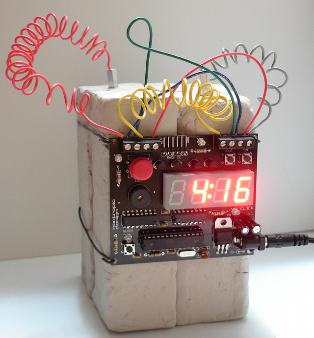
This may look like a dangerous device, but it’s really just an ordinary alarm clock — with a twist.
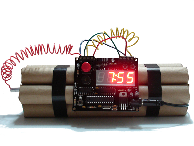
I thought it would be fun to build an alarm clock that looks just like the type of bomb that we always see in Hollywood movies. I certainly don’t know anything about how a real bomb might look, but in the movies they always have sticks of dynamite strapped together, a red digital readout, and a bunch of curly wires. Instead of just building an ordinary clock, I thought it should have a detonation sequence with a scary countdown just like in the movies. And why not make it “defusable” so I an try to stop the countdown by cutting the correct wire?
The Defusable Clock is a fully-functional alarm clock just like you’d expect (a normal beeping alarm, snooze alarm, etc.). But at any time you can press the big red button to start a scary countdown sequence exactly like bombs in Hollywood movies. There are 4 wires across the top of the clock. You have 10 seconds to choose the correct wire to cut: one wire stops the countdown and saves the day, two have no effect, and one will “detonate” the device immediately. These role of each wire is randomly assigned when the detonate button is pressed, so it’s a new challenge every time. Also, the wires are attached with screw terminals, so you can replace them easily. If you don’t want to actually cut the wires, you can just pull them out of the screw terminals if you keep the screws a little loose.
The microcontroller is an ATmega328 with the Arduino bootloader, so this clock is programmable with the Arduino IDE. The ATmega328 is certainly more powerful than needed for a clock, but this device has lots of inputs/outputs, and ATmega328 chips are now about the same price as the older ATmega168. It keeps very accurate time and requires a simple 9V “wall wart” power adapter. A special alarm mode lets you even use the countdown sequence as the alarm and require it to be defused when you wake up in the morning. What a stressful way to start the day!
We are going to offer this as an electronics kit later this fall. Only the electronics will be in the kit — nothing that looks like dangerous explosives! With some imagination, I’m sure you can make a great looking Defusable Clock for yourself, but don’t go scaring anyone with it, and don’t bring it anywhere near an airport, ok? The product page will have plenty of warnings not to use this kit for any evil purposes or get into trouble with your school, employer, or local law enforcement! There will also be a picture gallery where you can submit a picture of your clock after you build it.
UPDATE: the Defusable Clock kit is NOW AVAILABLE FOR PURCHASE!
I’m sure some of you will have some ideas and comments, so please leave them below. Keep in mind that this is no more dangerous than any other alarm clock, and yes, we have already spoken to a lawyer about all of this.
Here’s one more version I made using clay for plastic explosives:
Visualizing TV Dialog Using Closed Caption Data
Difficulty Level = 8 [What’s this?]

One of the coolest things you can do with the nootropic design Video Experimenter shield for Arduino is decode the closed caption data embedded in NTSC (North American) television broadcasts. I figured out how to do this and documented it in a another project, so if you want to understand all the details of how to capture and decode closed captions, refer to that project. With this project, I take it a step further and show how the spoken dialog embedded in a television show can be visualized on a computer in a “cloud” of words. This is the same type of cloud (often called a “tag cloud”) that you see on blogs, where the frequency of a particular word is reflected in the size of the word. More frequent == larger word.
Hardware Setup
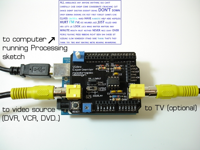
First, here’s how the hardware is set up. It’s really simple. The Video Experimenter needs a composite video feed from a TV tuner like a DVR (e.g. Tivo) or VCR. You can also use a DVD player because DVDs usually have closed captioning data. The USB cable connects to your computer where you run a Processing sketch (program) to visualize the words as they are decoded by the Arduino. The Processing sketch dynamically builds the TV cloud as the words are extracted from the closed caption stream!
Demo Video
Here’s a video where I show a TV cloud of spoken dialog being created dynamically. I superimposed a video of the television broadcast so you can correlate the broadcast with the Processing application, but note that the Processing application doesn’t acutally display the video. Words spoken with higher frequency are larger.
Example TV Clouds
I always have noticed that whenever I happen to see a US national news broadcast, all the commercials are for drugs. I guess only old people watch the news on TV anymore. Here’s a TV cloud of the commercials shown during NBC Nightly News. Can you guess which drugs are being advertised? Can you guess which maladies they claim to cure? Look at all those nasty side effects!
Here is a TV cloud made while watching a baseball game. For US readers familiar with baseball, can you guess which teams were playing? Answer is at the end of this post.
The Software
The Arduino sketch is fairly simple, and for details on how it works, please see the in-depth article about decoding closed captions.
This project is the “ExtractCaptionWords” example in the TVout library for Video Experimenter.
The Processing sketch reads words from the serial line and filters out any word less than 3 letters and some very common words like “the”, “and”, “for”, etc. This application relies on the very nice OpenCloud Java library, so you’ll need to download that and use it in your Processing environment. Create this structure in your Processing sketchbook libraries directory: opencloud/library/opencloud.jar
Download the Processing sketch
Answer
Answer to the baseball broadcast question: Kansas City Royals vs. Minnesota Twins (go Twins!)
Video Experimenter on the Seeeduino Mega
The nootropic design Video Experimenter shield uses some pretty advanced features of the Arduino’s ATmega328 microcontroller. One downside of this is that you can’t use the Video Experimenter shield on an Arduino Mega. Why? Well, the designers of the Arduino Mega didn’t connect a lot of the ATmega1280/ATmega2560 pins to headers on the board so that you could use them! And, as it turns out, the pins with key features utilized by the Video Experimenter are not connected to anything!
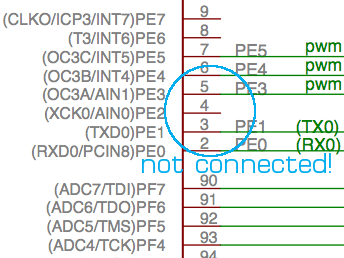
To perform video overlay, the Video Experimenter relies on an input capture pin (to capture the exact time that the pin has changed state). Even though the ATmega1280/ATmega2560 has 4 input capture pins, none of them are connected!
And to capture video images in the Arduino’s memory, Video Experimenter uses the analog comparator in the chip. But the AIN0 pin for the analog comparator is not connected! What were the Arduino Mega designers thinking?
Fortunately, there is the Seeeduino Mega. The guys at Seeed Studio broke out nearly all the pins on the ATmega1280 so that you can use them. I love the Seeeduino Mega because it provides so many pins on a rather small board.
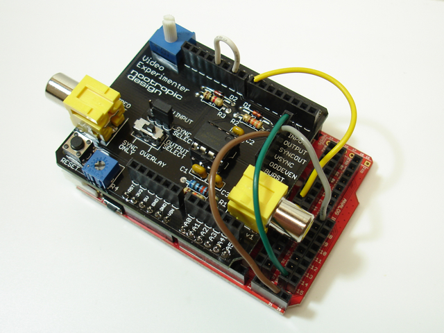
Simply make 5 connections with jumper wires and you can use the Video Experimenter on the Seeeduino Mega. No code changes necessary!
Here are the connections to make:
11 to 9 (white wire in picture above)
7 to 29 on the Seeeduino Mega (yellow wire)
INPUT pin on the Video Experimenter to PE2 on the Seeeduino Mega (green wire)
SYNCOUT pin on the Video Experimenter to PD4 on the Seeeduino Mega (gray wire)
VSYNC pin on the Video Experimenter to 21 on the Seeeduino Mega (brown wire)
Now you can use the Video Experimenter with an Arduino that has a more powerful processor. It really helps to have 8K of SRAM instead of 2K. Now you can do text and graphics overlay with higher resolutions, like 192×128. Have fun!
Digit Shield Limited Edition: Blue
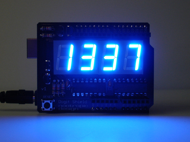
Blue Digit Shields are now available as a limited edition. I have only a very small stock of these fully assembled and tested Digit Shields for Arduino. Blue LEDs and LED displays are much more expensive than red and green, but I am able to offer these at the same price as assembled red and green Digit Shields. They are extremely bright and look very cool! Get one while you can!
Tutorial: PCB Design T-Shirt
I recently had the idea of printing a PCB design on a t-shirt. Since I don’t do my own silkscreening, I just wanted to upload my EAGLE PCB design to a custom t-shirt provider and have them do the hard part. In this post I’ll show you how you can do the same for your favorite board design. Mine turned out great!
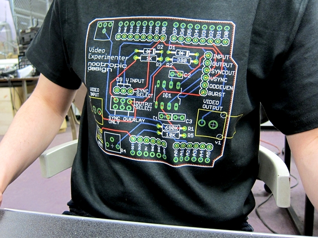
Photo by Paul Sobczak
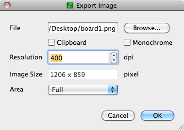
First, I exported my board design from EAGLE by choosing File -> Export, then picking Image from the next menu. You want your image to be high resolution, so increase the DPI value to at least 400 to give you a large image. Choose a file location for your large PNG file.
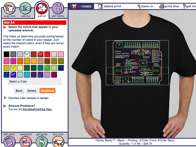
I then used Custom Ink to have the t-shirt made. I chose a black short sleeve Hanes Beefy-T. The shirt design tool makes it easy to upload an artwork image. After uploading, it asks you to choose the colors that are in the image. My standard Eagle board image has red, blue, white, green, and yellow. The colors you choose don’t have to exactly match your image — it’s just for accurate pricing.
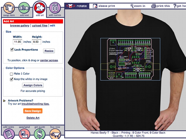
Then I resized the image so that it filled the front of the shirt. I also made sure to select the checkbox that says “keep the white in my image”.
Next, get a quote and order a shirt. Mine only cost $24.75 and shipping was free in the U.S. I thought this was a great price and was really happy with the result!
