Arduino-Controlled Mood Lamp Made with LEDs and Glass Vials
Difficulty Level = 6 [What’s this?]
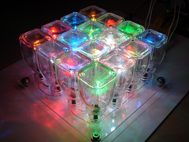
This is a mood lamp I build using 16 LEDs of different colors and small glass vials. The square bottoms of the vials look a lot like glass block, and the glass diffuses and scatters the light in beautiful ways. The software shows random patterns of light and the brightness of each LED can vary — they aren’t simply “on” or “off”.
The Arduino code is pretty complex because it implements PWM (pulse-width modulation) for all 16 LEDs. The Arduino board only has 5 PWM-capable pins, so providing PWM for all 16 pins is accomplished purely in the code. The lamp randomly displays different lighting patterns and can be really mesmerizing. Ok, I know you want to see it in action, so here it is (note that the music is just in the background — the lights are not reacting to it):
Construction
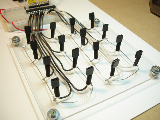
The base of the lamp is a piece of plexiglass about 5 inches square, and all of the wiring is on the underside of the plexi. Each of the 16 LEDs goes into a small socket made from two pins of a female header. I used sockets instead of soldering the LEDs directly so that I could rearrange the colors any way I like.
read more…
Wireless Robotics Platform: Cheap R/C Vehicle + Arduino + XBee + Processing
Difficulty Level = 8 [What’s this?]
UPDATE: Check out the new robotics platform project!
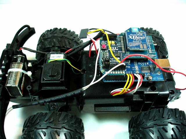
I built a wireless robotics platform from a cheap R/C car, an Arduino with XBee shield, small microswitch sensors, and a Processing program running on a remote computer to control the vehicle. The vehicle is completely controlled by the code running on the remote computer which allows very rapid prototyping of the code to tell the vehicle what to do and how to react to the sensor events received from the vehicle. I’m hoping this is a good way to teach my 9-year old son about programming.
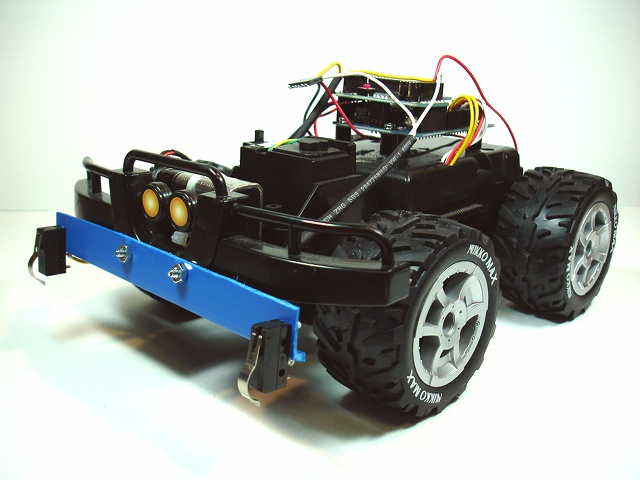
Wireless computer-controlled robotics platform built on cheap RC vehicle, Arduino microcontroller, and XBee radios
Before I get into details, here’s an overview of the features:
- All logic controlling the vehicle is performed in a Processing program running on remote computer. The Arduino program listens for commands from the remote computer.
- Bi-directional wireless communication over XBee radios with (theoretical) 1-mile range. I’ve accomplished 1/4 mile range with these radios.
- Sensor events are transmitted from the vehicle to the controlling computer. This vehicle has 3 microswitches – two on front bumper and one at the rear.
- Original circuitry of vehicle replaced with dual H-Bridge circuit to control drive motor and turn motor. Drive motor is controlled with variable speed.
- Power: Vehicle motors powered by 4 AA batteries. Arduino with XBee shield powered by 9V battery mounted at front of vehicle.
- Simple communications protocol: 2 byte commands from controller to vehicle, one byte sensor readings from vehicle to controller.
The Hardware
There’s nothing special about the configuration of the XBee radios. They are running the AT firmware (“transparent mode”) which allows them to simply exchange serial data. The Libelium XBee shield on top of the Arduino makes it easy to read/write serial data from Arduino code.
Inside the vehicle is a simple circuit board with an SN754410 quadruple half-H driver to drive the motors. The drive motor and turn motor are connected. I had to rip out the original circuit board (but I saved it!).
read more…
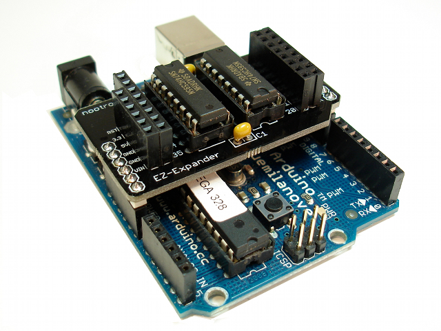
EZ-Expander Shield for Arduino
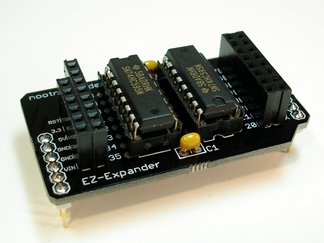
I’m happy to finally announce my new product, the EZ-Expander shield. After several months of hard work of sourcing parts, designing the PCB, and setting up a store, my first product is now available for purchase in the nootropic design store!
For all the technical details, go to the EZ-Expander page.
Arduino Police Lights
Difficulty Level = 4 [What’s this?]
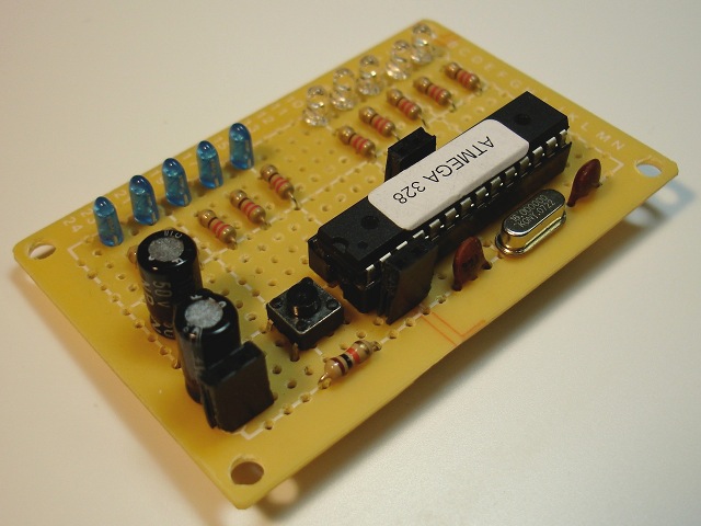
This is an amusing project inspired by flashing blue and red lights on police cars, ambulances, etc. This is a perf board Arduino with 5 blue and 5 red LEDs, and the Arduino code lights them up in a pattern similar to police lights.
First, the Arduino built on a perf board. It’s not hard to build your own Arduino. I use a real Arduino board to upload code to the ATMega328 chip, then just move it to the project board.
Now here it is in action — I really think if you don’t know what you’re looking at, it looks realistic in the dark.Here’s the code that makes it work. Notice that some of the LEDs are controlled using PWM; the second and fourth LED in each of the blue and red groups. I would invite people to build something similar and tweak this to get the most realistic effect possible!
#define NUM_OFF 3
#define DELAY 50
#define PWM_MIN 10
#define PWM_MAX 128

int blue[5];
int red[5];

void setup()
{
  blue[0] = 19;
  blue[1] = 5;
  blue[2] = 18;
  blue[3] = 6;
  blue[4] = 17;
  red[0] = 13;
  red[1] = 11;
  red[2] = 12;
  red[3] = 10;
  red[4] = 9;

  for(int i=0;i<5;i++) {
    pinMode(blue[i], OUTPUT);
    pinMode(red[i], OUTPUT);
  }
  randomSeed(analogRead(0));
}

void loop()
{
  allOn();
  analogWrite(blue[1], random(PWM_MIN, PWM_MAX));
  analogWrite(blue[3], random(PWM_MIN, PWM_MAX));
  analogWrite(red[1], random(PWM_MIN, PWM_MAX));
  analogWrite(red[3], random(PWM_MIN, PWM_MAX));


  for(int i=0;i<NUM_OFF;i++) {
    digitalWrite(blue[random(5)], LOW);
    digitalWrite(red[random(5)], LOW);
  }
  delay(DELAY);
}

void allOn() {
  for(int i=0;i<5;i++) {
    digitalWrite(blue[i], HIGH);
    digitalWrite(red[i], HIGH);
  }
}
Arduino-Controlled Lock with Keypad
Difficulty Level = 6 [What’s this?]
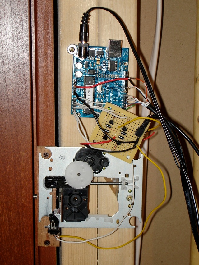
After tearing down an old CD player, I was inspired by the CD laser scanning assembly to build a door lock for my subterranean lab. The assembly has two motors: one for turning the CD (I’m not using this one) and one for slowly moving the laser across the CD’s surface. This second motor provides a nice linear motion that I wanted to use to build an electronically-controlled dead bolt lock for my lab.
Here’s the assembled lock. The circuit board in the middle is an H-bridge circuit I built to allow the motor to move in both directions. There are two position sensing switches so the Arduino senses when the motor has reached its limit in either direction. A 9V power supply powers the Arduino board, and a separate 5V supply drives the motor through the H-bridge. The dead bolt is literally a bolt — connected to the assembly with a piece of scrap circuit board — that travels through the door jamb and into the door.
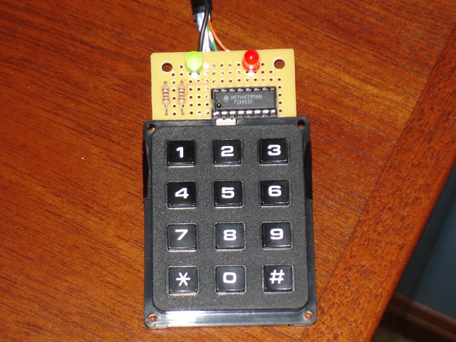
The black CAT5 cable connected to pins 2-8 goes through a small hole in the wall (under a desk) to the keypad on the outside of the lab (I wasn’t sure I wanted to permanently mount the keypad in the wall). The user types in the correct code and presses the # key to open or close the lock. The green LED indicates the door is unlocked. Red indicates locked.
Let’s see the lock in action. (While recording, I gave instructions to my son to lock and unlock using the keypad off camera.)
