Using a Relay Trigger with the Defusable Clock
Many of our Defusable Clock customers use the device in Airsoft competitions where participants must find the device and defuse it before the timer expires. A great thing to do in these games is to trigger a loud siren or smoke grenade when the timer reaches 00:00. The new version V2 of the clock has a connections for such a trigger and we are now selling relay modules in the nootropic design store.
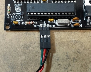
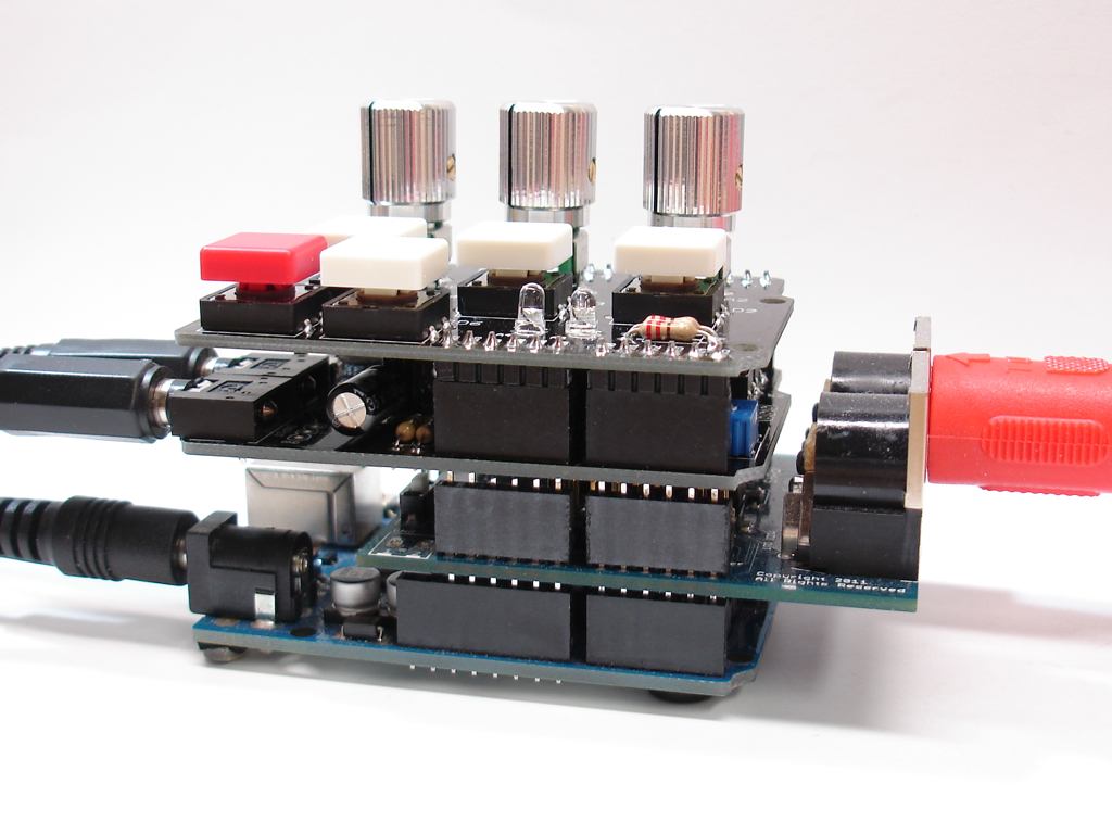
Below is a picture that shows how to connect a relay. The red wire is 5V and if you have an older kit it needs to be soldered to the output pin of the voltage regulator. It then connects to the 5V red wire on the relay module. The 5V output is the rightmost pin of the voltage regulator when looking at the front of the board. The green wire is the trigger connection and goes to the green wire on the relay module. The trigger ground connection is the black wire going to the relay module.

UPDATE: there is now a 5V pad next to the trigger and ground pads that you can use:
To send 9V to your destination device like a siren or smoke grenade, connect a wire to the + connection near the power connector, and a ground wire to the – connection. These are shown as yellow and black wires in the picture. This assumes you have a 9V input voltage to the clock. If you are using a different voltage like 12V or a 7.4V lipo battery, that’s fine. This is the voltage available on the + connection.
The black ground wire connects directly to your device. The positive voltage (yellow wire) connects to the relay module terminal marked “COM” (for “common”). The gray wire in the picture is connected to the relay terminal marked “NO” (for “normally open”) and this wire is the positive voltage to your siren or smoke grenade or whatever.
When the countdown reaches 00:00, the trigger voltage (green wire) will cause the relay to close and connect the 9V yellow wire to the gray wire, thus providing 9V to your external device for a duration of about 2.5 seconds while the clock goes through the “detonation” sequence. If you want power to be disconnected when the countdown reaches 00:00, connect the gray wire to the terminal marked “NC” (“normally closed”) instead.
Have fun, and as always, stay out of trouble!
Defusable Clock Used as Prop in ‘The Tomorrow People’ Episode
I am so excited that the nootropic design Defusable Clock was used as a prop in an episode of the new TV show The Tomorrow People on the CW Network! The episode “Kill or Be Killed” aired on October 30th, 2013. If you watch the episode online the Defusable Clock scene is at about 29:30. Here is a short clip showing the prop in action:
A special effects company providing services to this Warner Bros. production contacted me in August about using the Defusable Clock as a prop in the TV show. I worked with the propmaster to deliver several assembled devices quickly to the show’s shooting location in Vancouver, BC, Canada.
I then collaborated with a member of the special effects team to provide modifications to the Arduino code to better suit their needs. I doubled the display refresh rate to 976Hz to avoid flicker on camera. I removed the clock functionality and gave them better control over the timer display. I also modified the input functions so that wires connected to the terminal blocks could be used to control the timer dispaly. This way the crew could change timer from off-camera without having to touch the device.
They made a few other cosmetic changes, including removing my logo (!), but I think they did a great job using this device in the dramatic scene. It was a real thrill for me to watch!
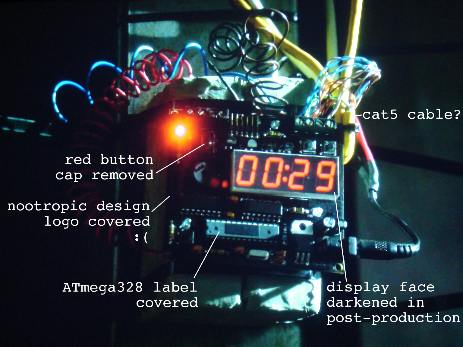
Still frame from “The Tomorrow People”
Audio Hacker Voice Changer
This Audio Hacker example shows how you can manipulate audio to radically change recorded samples. This project uses a technique called granular synthesis, to raise and lower the pitch of a sample. It’s easy to change the pitch of a sample by playing it slower or faster, but granular synthesis allows you to alter the pitch without changing duration of the sample. So if a recorded sample was 5 seconds long, we can play it back at a higher or lower pitch, but the played sample will still have a duration of 5 seconds.
The technique is rather complex, but it involves dividing the sample up into small fragments called “grains”. When playing back a sample, if we want the pitch higher, we play the grain at a higher speed, but we play it over and over again until it takes the same amount of time as the grain played at original speed. Likewise, to lower pitch, we play each grain at a slower speed, but move onto the next grain sooner so that the overall sample has the same duration.
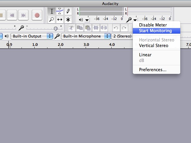
This technique introduces some noise, but it works really well with voice recordings. To send your voice into the Audio Hacker, I recommend using Audacity. Enable the monitoring feature for the microphone so that anything picked up by the computer’s microphone to the computer’s audio output, which is connected to the Audio Hacker input.
For this project I used the DJ Shield because it has 5 buttons and 3 pots. Record a sample with a button on D5, and playback with a button on D6. A potentiometer connected to A0 changes the pitch after recording. Before recording, set the A0 pot to the midpoint. When playing back a sample, use A0 to alter the pitch.
But there’s more! A potentiometer connected to A1 changes the size of the grains. And a potentiometer on A2 allows you to “stretch” each grain and play it multiple times. Now using all of these controls, we can do some really fun stuff! Here’s a video showing what you can do:
The Arduino sketch source code is an example in the Audio Hacker library: File->Examples->Audio Hacker->VoiceChanger.
Audio Hacker Drum Machine
This project really pushes the limits of what you can do with audio sampling on an Arduino! It is almost the same as the 3-Track Looper project so I recommend you read that first. Now instead of controlling a loop delay with a potentiometer, we can lay down a track by tapping out a rhythm that plays a sample. This project really works best if you use very short samples like drum sounds or words you say with your voice. Just as before, the tracks can be played back and mixed together.
Load the Audio Hacker example sketch File->Examples->Audio Hacker->DrumMachine. For this project, I used the DJ Shield because it provides all the buttons.
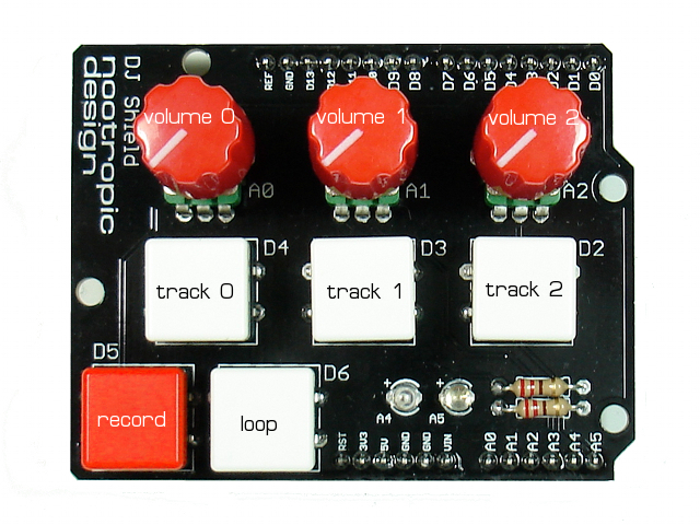
You can build it on a breadboard if you want:
Record button = D5
Loop button = D6
Track 0 button = D4
Track 1 button = D3
Track 2 button = D2
Track 0 volume = A0
Track 1 volume = A1
Track 2 volume = A2
When the record button is tapped (pressed and released), it toggles the “passthrough” mode for the input. That is, when the sketch starts, the input is passed through to the output so you can hear it, but you can enable/disable the passthrough by tapping the record button.
To record a track, first enable the audio passthrough so you can hear the audio signal. Now press and hold the record button down, then hold down a track button to record the track. Release the track button when done recording, or if you exhaust the memory size for that track, the output will stop. To play the track (just once), press the track button. Like I said before, this project works best with very short samples.
Before you set up any looping, record more sounds onto the other track buttons using this same technique. You can play your samples by simply pressing the track buttons.
Now it’s time to create some loops. To lay down a looping track using the sampled audio, first press and hold the loop button. Now tap out a rhythm on a track button. When you want your tapped rhythm to start repeating, release the loop button. Now while this track is looping, hold the loop button and tap out another rhythm on another track. Release the loop button to start that rhythm looping. The two loops will be mixed together, each playing the rhythm you tapped out. To stop the looping of a track, tap the track button. You can control the playback volume of each track with the potentiometer above the track button. This is an example of controlling volume digitally by changing the level of the output signal in code. It’s crude but needs to be fast.
If the controls are confusing, just play with it for a while until you get the hang of it. You can enable debugging by uncommenting the line #define DEBUG and open the Arduino serial monitor with speed 115200. This will show you information about what is going on in the sketch.
Performance Notes
This sketch is rather complicated so there are some performance compromises. The sample rate is 16 kHz and the samples are 8-bit audio.
The memory is divided up as follows: track 0 is on the first SRAM chip (128K) and can hold about 6 seconds. Tracks 1 and 2 split the second SRAM chip and are about 3 seconds each.
MIDI Triggering for Audio Hacker
This project shows you how you can use your Arduino+Audio Hacker as a MIDI instrument. The Arduino MIDI library makes it easy to read the MIDI commands that arrive on the Arduino serial port. I used a Rugged Circuits Flexible MIDI Shield for this project because it is, well, flexible. It allows you to specify which pins are used. Other MIDI shields are not likely to be pin compatible with the Audio Hacker, so I don’t recommend anything but the Rugged Circuits shield for this project. The MIDI shield stacks nicely with the Audio Hacker. I didn’t use the DJ Shield in in this project but I wanted to show this huge stack!
An external device like a digital piano or drum machine is the MIDI controller that sends MIDI commands to the Audio Hacker. So a MIDI cable runs from the controller’s MIDI OUT to the MIDI shield’s MIDI IN connection.
You will need the Audio Hacker library and the Arduino MIDI library installed in your sketchbook libraries folder. Load the Audio Hacker example sketch File->Examples->Audio Hacker->Sampler_MIDI.
The Audio Hacker is used to sample audio input from a computer or MP3 player, or whatever by holding down the S1 button on the shield. This sample can be played back with the S2 button, just as with the normal Sampler_12bit example sketch.
But when a note is played on the MIDI controller (e.g. piano) a MIDI message is received by the Audio Hacker sketch and the sample is played at a speed proportional to the note played. For example if a middle C note on a digital piano is pressed, then a “noteOn” message with value “60” will be sent to the Arduino and the sample will be played normally. If you play a higher note, the playback speed will be faster, raising the pitch. A note below middle C will slow down the playback and play a lower note.
Here it is in action:
