Connecting an Electret Microphone to the Audio Hacker
I like to use my computer’s microphone and audio output when I want to record my voice in the Audio Hacker, but you can also connect an electret microphone using a simple circuit. An electret microphone is handy for applications where you don’t want a computer. Electret microphones have polarity, so make sure you connect the positive/negative leads correctly in the circuit.
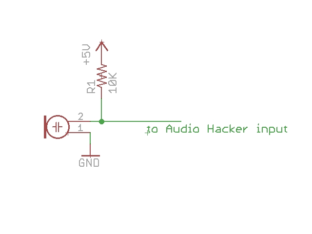
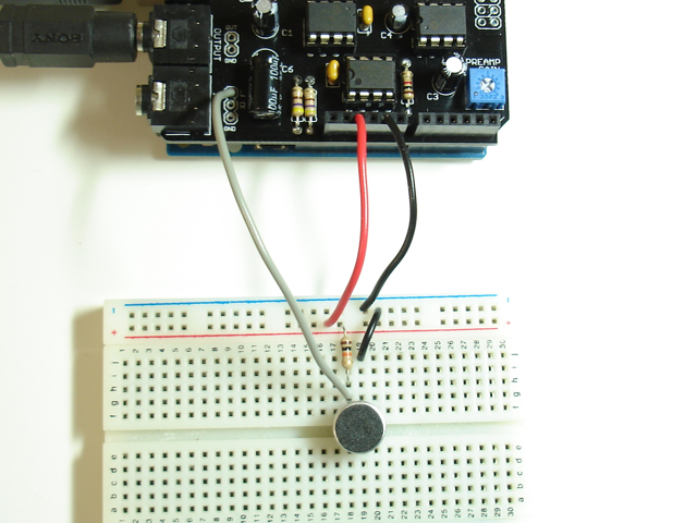
Since the output of the microphone is very weak, turn up the preamp gain on the Audio Hacker shield until you are happy with the level (probably all the way up!). The preamp provides up to 100X gain. Connect the microphone’s positive lead to one of the input pads. It doesn’t matter if you pick ‘L’ or ‘R’, or connect the microphone to both.
Another approach is to use this handy microphone breakout board from Sparkfun. It includes a 100X amp so you don’t need to amplify its signal with the Audio Hacker preamp.
Audio Hacker Echo Effect
This project allows you to use the Audio Hacker shield to manipulate an audio signal in realtime by adding an echo effect. This is achieved by constantly recording the incoming signal to memory. When reproducing the incoming audio on the output, we also mix in previously recorded signal from “the past”. By adjusting a potentiometer connected to A0, you can adjust the amount of delay that the echo has. The longer the delay, the further back into memory the program reads to get the echo signal. The echo is attenuated so that it is quieter than the signal being played through from the input. Attenuating the signal is achieved by simply dividing the value by 2, therefore reducing its volume by 6dB.
Load the Arduino sketch File->Examples->Audio Hacker->EchoEffect. Connect a potentiometer to A0. If you are unsure how to wire the potentiometer, see analog input tutorial. Set the pot to its lowest level. Connect an input source so we can create an echo effect of the input. Spoken word is much better for hearing an echo than music, so try using a talk radio station or a podcast. Now increase the potentiometer to increase the amount of echo.
If you want to know how long the echo is, uncomment the line #define DEBUG and open the Arduino serial monitor with speed 115200.
Here is what the echo effect sounds like. While recording this, I changed the echo delay by using a potentiometer so you could hear the difference between short delays and long delays.
To send my voice into the Audio Hacker, I run Audacity on my computer and enable the monitoring feature for the microphone.
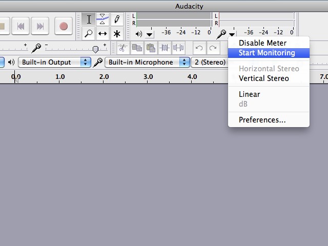
This sends anything picked up by the computer’s microphone to the computer’s audio output, which is connected to the Audio Hacker input. I highly recommend Audacity which is free!
12-bit and 8-bit Audio Samplers
This project is an introduction to the new nootropic design Audio Hacker shield. The first sketch you should use with the Audio Hacker is the 12-bit Sampler. Install the Audio Hacker Arduino library in your Arduino sketchbook, then choose the menu item File->Examples->Audio Hacker->Sampler_12bit.
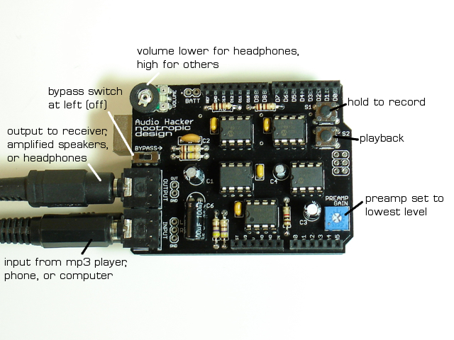
Connect an audio source to the input jack of the Audio Hacker. For example, an MP3 player or computer with the volume at a high level. Make sure the bypass switch is in the left position (no bypass) and that the preamp gain potentiometer is set to the lowest level (counterclockwise). Connect the Audio Hacker output jack to amplified computer speakers, an input to a stereo receiver, or use headphones (but turn the Audio Hacker volume down first!).
The audio input signal is sampled and reproduced on the output at 44.1 kHz. Everything you are hearing has been processed by the Arduino code. To compare it to the original signal, move the bypass switch to the right position. Now you are hearing the original signal (but after it has been summed to a mono signal). Can you hear a difference between the original and the audio sampled and reproduced by Arduino code?
With the bypass off (left position), press S1 to record the audio to memory (up to 8.6s) with a sample rate of 22 kHz. Press S2 to play it back.
Code
Sampling and playing audio requires precise timing. The Arduino timer1 is used to run an interrupt service routine (ISR) at a very specific frequency. The sample rate determines how often the interrupt service routine (ISR) is invoked. In order to efficiently store 12-bit audio samples, two samples are “packed” into 3 bytes before they are written to memory. To make this process efficient, read and write memory operations alternate. That is, we only write to memory on “odd” numbered ISRs and read from memory on “even” numbered ISRs.
8-bit Sampler
The 8-bit sampler File->Examples->Audio Hacker->Sampler_8bit is simpler code and can record longer samples. If you want to understand the Audio Hacker library API, this sketch will help you. Since this approach is simpler, we don’t trade off read and write operations on alternating ISRs. You will likely hear a sound quality difference, though. If you listen to samples with headphones you may hear background noise (like a hiss) in the samples compared to the 12-bit version.
Sample rate adjustments
You can make your own adjustments to the recording sample rate by changing the value of the variable recordingSampleRate. For example, set the value to 18000 for a sample length of 10.4 seconds. The lower the rate, the longer the sample you can record, but quality starts to suffer. See this table for information on sample lengths.
Adjustable playback rate
You can use a potentiometer connected to A0 to adust the playback rate of the recorded sample.
To enable this feature, make a minor code change to set adjustablePlaybackSpeed = true;. Arduino will prompt you to save your changed sketch to another location. Now connect a potentiometer to A0. If you are unsure how to wire it, see analog input tutorial. Then you can play back a sample with a different speed. Set the pot to midway point when you record, then adjust. Fun, huh?
Arduino Backpack Board for RGB Matrix Panel
A while back, I did a project using a 32×16 RGB LED matrix panel from Adafruit but found that connecting an Arduino to the panel was a real wiring mess. So I decided to design a small Arduino “backpack” board that snaps right onto the back of the panel so that there’s no more wiring frustration.
UPDATE! This is now available in our store!!!

The board is a simple Arduino that has an 8×2 female header so that it can snap right onto the back of the RGB panel. The board also includes a 2.1mm power jack for a 5V power supply, a 6 pin serial header for easy programming using a USB-serial cable, and a 2-pin terminal block for connecting to the panel’s power terminals.

I had the board manufactured by Laen’s PCB service at Dorkbot PDX, which is a great way to get boards made in small quantities for projects just like this. Customers of Laen will instantly recognize his signature purple boards.
I’m so happy with this simple solution for driving my panel that I used it for a display sign when I exhibited at the Twin Cities Maker “Minne-Faire” in April. I wrote some animations for the Arduino backpack to display, and they look great. The video doesn’t do them justice because it’s really hard to capture bright LEDs on video. This panel is blindingly bright!
Feel free to download the source for this demo.
I’m not selling this board as a product because the market is probably too small, but if you have one of these RGB panels, you can make your own. Just download the design files and have the PCB manufactured!


Tabasco Bottle LED Mood Lamp
I love Tabasco and always though that their cute little miniature bottles could be the basis for a great specialty lamp. I was very happy to find that a 3mm LED fits perfectly in the bottle opening of the miniature bottles. By designing a custom circuit board I was able to make a lamp that looks like a bundle of dried peppers.

Each bottle is individually controlled with a TLC5940 16-channel PWM driver. The software running on the ATmega328 is Arduino code that implements different lighting effects. Here it is in action:
Hardware
I designed a circuit board for the ATmega328 and the TLC5940. This is basically a custom Arduino and the design files are available below in case you want to make one. The LEDs connect from the bottom of the board. I am using a 5V regulated power supply, so there’s no need for an on-board voltage regulator. I included a 6-pin serial header for easy Arduino programming and mounting holes on the corners so I can hang it from wires. I also included a tactile button in case I wanted to allow some input to control the lamp (currently unused). Also note the Tabasco logo right on the board silkscreen!

I photographed the assembly process so you could see how I constructed the lamp.
 1. Make two holes in each cap using a small nail |
 2. Insert a 3mm LED into the cap |
 3. Ensure the LED is in the center |
 4. Connect wires by bending the leads. Make sure they don’t short! |
 5. Carefully solder and clip the leads. |
 6. Enclose in heat shrink tubing. |
 7. Twist wires and weave together. |
 8. Keep going! |
 9. Insert wires into underside of board. |
 10. Now just solder and clip the wires. |
Software
Here is the Arduino code running on the lamp. I used the TLC5940 Arduino library to control the PWM driver. You can download the code from here.
#include "Tlc5940.h"

#define NPINS 16
#define NVISUALIZATIONS 6
#define NFUNCTIONS 3
#define BUTTON 2

// pointers to the current and last visualizations
void (*visualization)() = rise;
void (*lastVisualization)() = rise;

// array of visualizations
void (*visualizations[NVISUALIZATIONS])() = {throb, blinkRandom, onOff, upDown, rise, fall};

// An array of all the functions.
int (*allFunctions[NFUNCTIONS])(float x) = {linear, sine, exponential};


// Each pin has a function associated with it.  The function determines how the brightness
// of the LED changes over time.
int (*function[NPINS])(float x);

// The x values for the function associated with each LED.  The x value is the current position along
// the x axis for the function.  There are are 256 x values on the x axis.  That is, the domain of the
// function is [0-255].
float x[NPINS];

// dx describes (for each LED) how the x value changes over time.  If dx=1, then x is increased by 1
// for each duty cycle.  If dx = -1, it is decreased by 1.  If dx=5, then the brightness of the LED will
// change faster according to the function because we are moving along the function curve faster.
float dx[NPINS];

// y is the current value of the function at x.  If the function is 'linear' and x=128, then y=128.
// If the function is 'sine' and x=10, then y=0x03.  See the sineValues array below that defines
// the sine function.
int y[NPINS];

// For each LED we can specify whether the x value should "wrap" around when reaching the end.
// There are 256 possible values for x [0-255].  If we reach 255 and dx=1, then we can wrap around
// back to x=0 if wrapFunction=true.  If false, then adding 1 to 255 keeps x=255.
boolean wrapFunction[NPINS];

// Definition of sine function.  Array lookup executes faster than actually computing the sine.
unsigned char sineValues[] = {
  0x00,0x00,0x00,0x00,0x00,0x00,0x01,0x01,0x02,0x03,0x03,0x04,0x05,0x06,0x07,0x08,
  0x09,0x0a,0x0c,0x0d,0x0f,0x10,0x12,0x13,0x15,0x17,0x19,0x1b,0x1d,0x1f,0x21,0x23,
  0x25,0x27,0x2a,0x2c,0x2e,0x31,0x33,0x36,0x38,0x3b,0x3e,0x40,0x43,0x46,0x49,0x4c,
  0x4f,0x51,0x54,0x57,0x5a,0x5d,0x60,0x63,0x67,0x6a,0x6d,0x70,0x73,0x76,0x79,0x7c,
  0x80,0x83,0x86,0x89,0x8c,0x8f,0x92,0x95,0x98,0x9c,0x9f,0xa2,0xa5,0xa8,0xab,0xae,
  0xb0,0xb3,0xb6,0xb9,0xbc,0xbf,0xc1,0xc4,0xc7,0xc9,0xcc,0xce,0xd1,0xd3,0xd5,0xd8,
  0xda,0xdc,0xde,0xe0,0xe2,0xe4,0xe6,0xe8,0xea,0xec,0xed,0xef,0xf0,0xf2,0xf3,0xf5,
  0xf6,0xf7,0xf8,0xf9,0xfa,0xfb,0xfc,0xfc,0xfd,0xfe,0xfe,0xff,0xff,0xff,0xff,0xff,
  0xff,0xff,0xff,0xff,0xff,0xff,0xfe,0xfe,0xfd,0xfc,0xfc,0xfb,0xfa,0xf9,0xf8,0xf7,
  0xf6,0xf5,0xf3,0xf2,0xf0,0xef,0xed,0xec,0xea,0xe8,0xe6,0xe4,0xe2,0xe0,0xde,0xdc,
  0xda,0xd8,0xd5,0xd3,0xd1,0xce,0xcc,0xc9,0xc7,0xc4,0xc1,0xbf,0xbc,0xb9,0xb6,0xb3,
  0xb0,0xae,0xab,0xa8,0xa5,0xa2,0x9f,0x9c,0x98,0x95,0x92,0x8f,0x8c,0x89,0x86,0x83,
  0x80,0x7c,0x79,0x76,0x73,0x70,0x6d,0x6a,0x67,0x63,0x60,0x5d,0x5a,0x57,0x54,0x51,
  0x4f,0x4c,0x49,0x46,0x43,0x40,0x3e,0x3b,0x38,0x36,0x33,0x31,0x2e,0x2c,0x2a,0x27,
  0x25,0x23,0x21,0x1f,0x1d,0x1b,0x19,0x17,0x15,0x13,0x12,0x10,0x0f,0x0d,0x0c,0x0a,
  0x09,0x08,0x07,0x06,0x05,0x04,0x03,0x03,0x02,0x01,0x01,0x00,0x00,0x00,0x00,0x00
};


void setup() {
  randomSeed(analogRead(5));
  pinMode(BUTTON, INPUT);
  digitalWrite(BUTTON, HIGH);
  Tlc.init(0);
}

void loop(){

  lastVisualization = visualization;
  visualization = visualizations[random(NVISUALIZATIONS)];

  // call the current visualization function
  (*visualization)();

}

// Execute n duty cycles.
// First we call stepXAll() which adds dx to each x value.  This moves the LED along the x axis
// of its function.
// Then, for each LED,  we compute the new y value for the current x value according to which
// function (linear, sine, exponential) that is associated with the LED.
// For any LED that is supposed to be on at all (any pin with a y value greater than 0), we turn it on.
// A duty cycle is a loop of 256 steps executed quickly in succession.  At the beginning of the duty cycle
// each LED that has a value of y>0 will be on.  At each step we see if there are any LEDs that need
// to be turned off for the remainder of the duty cycle.  So if an LED has y=100, we will turn it off at
// step 100.  That LED will have been on for the first 100 steps of the duty cycle and off for the
// remaining 156 steps.  So it is dimmer.  If an LED has y=255, then it will remain on during the whole
// duty cycle and be at full brightness.  An LED with a low value y=10 will be very dim because we turn
// it off very early in the duty cycle.
// This 256 step cycle is executed n times as specified by the input parameter n.

void dutyCycle(int n) {
  for(int i=0;i<n;i++) {
    stepXAll();
    computePinValueAll();
    for(int p=0;p<NPINS;p++) {
      Tlc.set(p, y[p]*16);
    }
    Tlc.update();
    delay(10);
  }
}

void stepXAll() {
  for(int p=0;p<NPINS;p++) {
    stepX(p);
  }
}

// Increment the x value for pin p by the value dx.
// Wrap the function around back to 0 (or back to 255)
// if wrapFunction is true for the pin p.
void stepX(int p) {
  x[p] = x[p] + dx[p];
  if (wrapFunction[p]) {
    if (x[p] > 255) {
      x[p] = x[p] - 256;
    } else if (x[p] < 0) {
      x[p] = x[p] + 256;
    }
  } else {
    if (x[p] > 255) {
      x[p] = 255;
    } else if (x[p] < 0) {
      x[p] = 0;
    }
  }
}


void computePinValueAll() {
  for(int p=0;p<NPINS;p++) {
    computePinValue(p);
  }
}

// Compute value y for pin p.
// Apply the function by invoking it with the x value.
void computePinValue(int p) {
  y[p] = (*function[p])(x[p]);
}


//////////////////////////////////////////////////////////////////////////////////
// Mathematical Functions
//////////////////////////////////////////////////////////////////////////////////

int linear(float x) {
  return (int)(x + 0.5);
}

int sine(float x) {
  return sineValues[(int)x];
}

int exponential(float x) {
 return (int) (255.0 * pow(50, ((x/127.5)-2)));
}


//////////////////////////////////////////////////////////////////////////////////
// Visualizations
//////////////////////////////////////////////////////////////////////////////////

// Do 30 blinks.  Each LED that is blinked will fade
// quickly down to 0 according to the exponential function.
void blinkRandom() {
  for(int p=0;p<NPINS;p++) {
    function[p] = exponential;
    wrapFunction[p] = false;
    x[p] = 0;
    dx[p] = -4;
  }

  for(int i=0;i<30;i++) {
    int p = random(0, NPINS);
    x[p] = 255;
    dutyCycle(10);
  }
}

void onOff() {
  allOff();

  for(int p=0; p<NPINS; p++) {
    x[p] = 0;
    dx[p] = 0;
    function[p] = linear;
    wrapFunction[p] = false;
  }

  int on = 0;
  int p;
  int d;
  while (on < NPINS) {
    p = random(0, NPINS);
    if (x[p] == 0) {
      on++;
      x[p] = 255;
      dutyCycle(1);
      d = 200 - (on * 10);
      delay(d);
    }
  }

  delay(1000);
  while (on > 0) {
    p = random(0, NPINS);
    if (x[p] == 255) {
      on--;
      x[p] = 0;
      dutyCycle(1);
      d = 40 + (on * 10);
      delay(d);
    }
  }

  delay(100);
}


void throb() {
  eachDown();

  float minSpeed = 0.4;
  float maxSpeed = 1.0;

  // Set random speeds for LEDs
  for(int i=0;i<NPINS;i++) {
    dx[i] = minSpeed + (random(0, 17) * ((maxSpeed - minSpeed) / NPINS));
  }

  for(int p=0; p<NPINS; p++) {
    function[p] = sine;
    wrapFunction[p] = true;
  }

  // Run for a while.  Each pin will throb according to sine wave.
  dutyCycle(random(500, 2000));

  eachDown();
  delay(500);
}


void fall() {
  int down[NPINS] = {5, 0, 15, 9, 11, 4, 2, 3, 7, 12, 14, 1, 8, 6, 10, 13};

  allOff();
  for(int p=0; p<NPINS; p++) {
    function[down[p]] = linear;
    wrapFunction[down[p]] = false;
    x[down[p]] = 0;
    dx[down[p]] = 8;
    dutyCycle(8);

  }
  delay(200);
  allOff();


}

void rise() {
  int up[NPINS] = {13, 10, 6, 8, 1, 14, 12, 7, 3, 2, 4, 11, 9, 15, 0, 5};

  allOff();
  for(int p=0; p<NPINS; p++) {
    function[up[p]] = linear;
    wrapFunction[up[p]] = false;
    x[up[p]] = 0;
    dx[up[p]] = 8;
    dutyCycle(8);

  }

  delay(200);
  allOff();


}
void upDown() {
 allUp();
 allDown();
}


void allUp() {
  if (lastVisualization == allUp) {
    return;
  }

  for(int p=0; p<NPINS; p++) {
    x[p] = y[p];
    dx[p] = 1.0;
    function[p] = linear;
  }
  dutyCycle(256);
}

void allDown() {
  if (lastVisualization == allDown) {
    return;
  }

  for(int p=0; p<NPINS; p++) {
    x[p] = y[p];
    dx[p] = -1.0;
    function[p] = linear;
  }
  dutyCycle(256);
}


void eachDown() {
  boolean done = true;

  if (lastVisualization == eachDown) {
    return;
  }

  for(int p=0; p<NPINS; p++) {
    x[p] = y[p];
    dx[p] = -1;
    function[p] = linear;
    wrapFunction[p] = false;
  }

  done = false;
  while (!done) {
    dutyCycle(1);
    done = true;
    for(int p=0; p<NPINS; p++) {
      if (y[p] > 0) {
        done = false;
        break;
      }
    }
  }
}

void allOn() {
  for(int p=0; p<NPINS; p++) {
    function[p] = linear;
    x[p] = 255;
    dx[p] = 0;
  }
  dutyCycle(1);
}

void allOff() {
  for(int p=0; p<NPINS; p++) {
    function[p] = linear;
    x[p] = 0;
    dx[p] = 0;
  }
  dutyCycle(1);
}
Hardware Design Files
The schematic and board design are open source hardware, so you are welcome to have a board fabricated yourself! Download the design files here.


