Difficulty Level = 5 [What’s this?]
UPDATE: Also see this project for an easy way to display a temperature reading: Digit Shield Temperature Display.
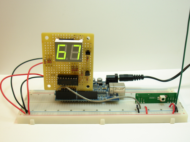
A while back, I did a wireless temperature sensor project using XBee radios. XBee radios are really powerful devices with good reliability and the ability to read and transmit sensor readings without a microcontroller. BUT, they are difficult for people to configure, the documentation is hard to understand, and it’s really difficult to parse the API data packets at the receiving station. So I decided to try the same project using inexpensive RF devices. I used a 434MHz transmitter ($4) and receiver ($5) from Sparkfun, and had great success with these cheap devices. I also used a simple LM34 Fahrenheit temperature sensor, two Arduinos (one was a homemade breadboard version), and a two-digit LED display to show the temperature at the receiver end.
The Receiver
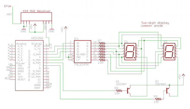
I used a single 74LS247 BCD to 7-segment driver chip for the display. The segment pins of the two digits are connected together, so I need to multiplex between the digits to show only one at a time. The multiplexing is so fast, there’s no flicker. The segments have common anodes and I used two PNP transistors to provide current to the anodes. Don’t ever drive the anodes directly from an Arduino output pin because it’s too much current!The RF receiver’s data pin is connected to the RX pin on the Arduino so we can just use the Serial library to read data at a slow 1200 bps. That is fast enough for temperature sensor readings. A 17cm antenna (the green wire) is attached to the ANT pin on the RF receiver.
Another important note is that the multiplexing between the two display digits is handled in an interrupt handler. The loop() code never has to do anything with the display. Timer2 is configured to fire an interrupt when the timer2 counter overflows, so the ISR near the end of this code runs about every 2ms and simply toggles which display is active. This is fast enough to provide perfectly smooth display without any fuss. All the register manipulation in the setup() method is the configuration of Timer2. I really like this way of handling the multiplexing automatically. You can download the code here.
#define PACKET_HEADER_SIZE 3
#define PAYLOAD_SIZE 1
#define CHECKSUM_SIZE 1
#define PACKET_SIZE (PACKET_HEADER_SIZE + PAYLOAD_SIZE + CHECKSUM_SIZE)
#define ADDR 1

byte temp = 0;
byte d1; // left digit
byte d2; // right digit
byte digitToggle = 0;

const byte packetHeader[PACKET_HEADER_SIZE] = {0x8F, 0xAA, ADDR};

void setup()
{
  Serial.begin(1200);

  for(int i=2;i<=7;i++) {
    pinMode(i, OUTPUT);
  }
  digitalWrite(6, HIGH);
  digitalWrite(7, HIGH);

  // Disable the timer overflow interrupt
  TIMSK2 &= ~(1 << TOIE2);

  // Set timer2 to normal mode
  TCCR2A &= ~((1 << WGM21) | (1 << WGM20));
  TCCR2B &= ~(1 << WGM22);

  // Use internal I/O clock
  ASSR &= ~(1 << AS2);

  // Disable compare match interrupt
  TIMSK2 &= ~(1 << OCIE2A);

  // Prescalar is clock divided by 128
  TCCR2B |= (1 << CS22)  | (1 << CS20);
  TCCR2B &= ~(1 << CS21);

  // Start the counting at 0
  TCNT2 = 0;

  // Enable the timer2 overflow interrupt
  TIMSK2 |= (1 << TOIE2);
}

void loop() {
  temp = readByte();
  setValue(temp);
}

byte readByte() {
  int pos = 0;
  byte val;
  byte c = 0;

  while (pos < PACKET_HEADER_SIZE) {
    while (Serial.available() == 0); // Wait until something is available
    c = Serial.read();

    if (c == packetHeader[pos]) {
      if (pos == PACKET_HEADER_SIZE-1) {
        byte checksum;

        // Wait until something is available
        while (Serial.available() < PAYLOAD_SIZE + CHECKSUM_SIZE);
        val =  Serial.read();
        checksum =  Serial.read();

        if (checksum != (packetHeader[0] ^ packetHeader[1] ^ packetHeader[2] ^ val)) {
          // Checksum failed
          pos = -1;
        }
      }
      pos++;
    } else {
      if (c == packetHeader[0]) {
        pos = 1;
      } else {
        pos = 0;
      }
    }
  }
  return val;
}

void setValue(byte n) {
  d1 = n / 10;
  d2 = n % 10;
}

void setOutput(byte d) {
  // This is more complex because the 74LS247 inputs are on
  // nonconsecutive Arduino output pins (for ease of soldering).
  PORTD &= ~0x3C; // turn off digital pins 2-5
  if ((d & 0x1) > 0) {
    // 74LS247 input A connected to Arduino pin 5
    PORTD |= (1 << PORTD5);
  }
  if ((d & 0x2) > 0) {
    // 74LS247 input B connected to Arduino pin 2
    PORTD |= (1 << PORTD2);
  }
  if ((d & 0x4) > 0) {
    // 74LS247 input C connected to Arduino pin 3
    PORTD |= (1 << PORTD3);
  }
  if ((d & 0x8) > 0) {
    // 74LS247 input D connected to Arduino pin 4
    PORTD |= (1 << PORTD4);
  }
}

// Interrupt service routine is invoked when timer2 overflows.
ISR(TIMER2_OVF_vect) {
  TCNT2 = 0;
  if (digitToggle == 0) {
    PORTD |= (1 << PORTD7);  // turn off digit 2
    setOutput(d1);
    PORTD &= ~(1 << PORTD6); // turn on digit 1
  } else {
    PORTD |= (1 << PORTD6);  // turn off digit 1
    setOutput(d2);
    PORTD &= ~(1 << PORTD7); // turn on digit 2
  }
  digitToggle = ~digitToggle;
}
The Transmitter
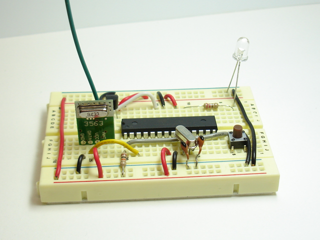
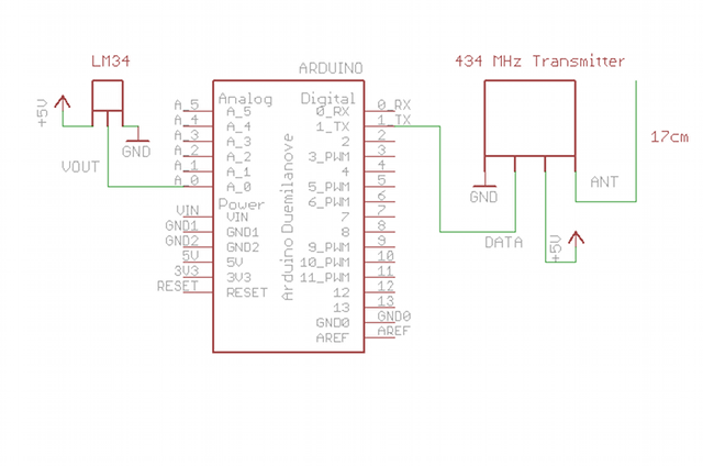
The unfortunate thing about using the RF transmitter is that it's a lot dumber than an XBee radio (but a lot cheaper, too). It has no ability to read the voltage on a pin and transmit it, so I had to use a microcontroller of some sort. At first I wanted to use an ATtiny13, but it has no UART for the serial transmission control. Then I wanted to use my ATtiny2313 which does have a UART, but doesn't have an analog to digital converter (ADC)! The smallest AVR microcontroller that I own that has both ADC and UART is the ATmega328. At this point I figured I might as well use a full-blown Arduino. I don't have two Arduinos so I built a breadboard version for use at the transmitter. You can just use a regular Arduino if you have one handy, or team up with a friend who has one.An LM34 temperature sensor outputs a variable voltage depending on the temperature. The mapping is extremely simple: 10mV for every Fahrenheit degree. So, at 72 degrees F, the output is 720mV. The Arduino TX pin is simply connected to the data pin on the transmitter.
Here's the schematic. There's an LED attached to pin 13 that I blink every time a sensor reading is transmitted (not shown in schematic).
#define SENSOR_ANALOG_PIN 0
#define LED_PIN 13
#define PACKET_HEADER_SIZE 3

#define ADDR 1

const byte packetHeader[PACKET_HEADER_SIZE] = {0x8F, 0xAA, ADDR};

byte temp;

void setup() {
  Serial.begin(1200);
  pinMode(LED_PIN, OUTPUT);
}

void loop() {
  digitalWrite(LED_PIN, HIGH);
  readTemp();
  writeByte(temp);
  digitalWrite(LED_PIN, LOW);
  delay(1000);
}

void readTemp() {
  byte reading = analogRead(SENSOR_ANALOG_PIN);
  int mv = ((float)(reading/1023.0)) * 5000;
  temp = mv / 10;
}

// Sends an unsigned int over the RF network
void writeByte(byte val) {
  byte checksum = (packetHeader[0] ^ packetHeader[1] ^ packetHeader[2] ^ val);
  Serial.write(packetHeader, PACKET_HEADER_SIZE);
  Serial.write(val);
  Serial.write(checksum);
}
That's all there is to it! This setup allowed me to transmit sensor readings reliably throughout my home, especially with a 17cm (1/4 wavelength of 434Mhz signal) antenna at the transmitter and receiver.

@Seth, I would try a simple program that just displays a number. Then you can know whether your display is wired correctly.
Michael, there is nothing that people are asking that they couldn’t find online or in a book. They are just being lazy. You can not teach people that only want an instant answer and won’t help themselves. I get annoyed just reading the inane questions. Why don’t you just leave your comments section open for a couple of weeks then move on.
Hello Micheal,
I am using two Arduino Uno’s and a 434 MHz receiver and transmitter. After successfully sending a number to the receiver, I attached the rest of the circuit am still nothing? I am getting a double blinking zero. Any advice?
Michael,
So I don’t think the circuit is multiplexing. All I am getting are double numbers. But I downloaded the code from your site, so I am not sure what exactly has gone wrong. Just thought I would share that, please any information would be extremely helpful.
Are you sure your anode aren’t connected together? Are you sure you’ve wired everything the same as I did? I’m not sure how I did everything as this was years ago.
Michael,
With the code written above, could you multiplex any faster?
Michael,
I was wondering do you have to declare the Tx and/or Rx pins in either of the codes?
thanks
This is exactly what I have been looking for!!!…Thanks for sharing this tutorial! Now my only question would be how would you use the temperature reading to cause something to turn on or off? For instance, when the temperature drops below 80 degrees a fan turns on. I understand how to do everything with wires, just a little confused as to how I would do this remotely. Do you think the remote controlled outlets will be a good place to start?
I’d consider using a relay to turn the fan on.
HI.sir .which type of ardino board u used in this circuit
muthupandi: Arduino Duemilanove. Uno also works.
Hi sir, Can I use arduino board in receiver also? and from where it is getting power?
The project explains clearly that an Arduino is part of the receiver. See the picture? The Arduino is powered however you’d like.
Sir, Can i try it with 8051 also? or please suggest some inexpensive alternative for arduina…..and thanx for reply
i would like to ask you if the library VirtualWire was not used in this codes? thanks
ralph, no the VirtualWire lib was not used. See the code above. It’s all there for you to read.
Where i will connect 8 and 16 pin of the 74LS247? The 7-seg only displays 77 and i use battery
Pin 8 is ground, pin 16 if +5V
Hey I am making an induction cooktop. And I will be using temperature sensor to measure the temperature of the Hot vessel used for cooking. Is it fine if I use LM34 for that. I want to transmit the temperature readings as you did through wireless transmitter and receiver to the receiving side micro controller.
Sends an unsigned int over the RF network
void writeByte(byte val) {
byte checksum = (packetHeader[0] ^ packetHeader[1] ^ packetHeader[2] ^ val);
Serial.write(0xF0);
Serial.write(packetHeader, PACKET_HEADER_SIZE);
Serial.write(val);
Serial.write(checksum);
}
can you please explain me this part. please
I’m not sure what you want explained. It computes a checksum, then sends the data plus the checksum.
Hi Michael, it rely works well, but i want to change lm 34 to lm35, can i get program for lm35/celsius for transmitter and is dat same program i must use in receiver?
I want to be able to receive multiple wireless temperature inputs how can I differentiate them?
@Rick,
You’d need to code specifically for that situation. Maybe just identify the readings from the 2 sensors with a distinct identifier when you send the data.
Really Good Work………..
Ravi Saini
http://www.nrdcentre.com
hi michael, may I know where the rf transmitter and receiver located in the Eagle library? I want to do circuit simulation, using the Eagle Software..I’m using these components with the HT12D and HT12E..really appreciate your help,..thank you very much and I hope you can reply me soon..
Hi, i’m new in arduino, i need help, i try to use a HC-sr04 prox sensor and send the data thru 433 rf module, and use a second arduino (receiver) to print the data in a serial console.
i only have a lcd 16×2 display, and i am a newbie in programming arduino….please i need help coding the receiver program
i only have a lcd 16×2 display, and i am a newbie in programming arduino….please i need help coding the receiver
program to use the lcd display
Israel, that is no way to get help. You can’t ask others to drop their projects to help you with yours.
Hello, Please Help!
For me this project is not working.
I use for receiver Arduino Uno and 433Mhz receiver.
Sketch:
#define PACKET_HEADER_SIZE 3
#define PAYLOAD_SIZE 1
#define CHECKSUM_SIZE 1
#define PACKET_SIZE (PACKET_HEADER_SIZE + PAYLOAD_SIZE + CHECKSUM_SIZE)
#define ADDR 1
byte temp = 0;
byte d1; // left digit
byte d2; // right digit
byte digitToggle = 0;
const int d3 = 8;
const int negatif = 9;
const byte packetHeader[PACKET_HEADER_SIZE] = {0x8F, 0xAA, ADDR};
void setup()
{
Serial.begin(9600);
for(int i=2;i<=7;i++) {
pinMode(i, OUTPUT);
}
digitalWrite(6, HIGH);
digitalWrite(7, HIGH);
pinMode(d3, OUTPUT);
pinMode(negatif, OUTPUT);
digitalWrite(d3, LOW);
digitalWrite(negatif, HIGH);
// Disable the timer overflow interrupt
TIMSK2 &= ~(1 << TOIE2);
// Set timer2 to normal mode
TCCR2A &= ~((1 << WGM21) | (1 << WGM20));
TCCR2B &= ~(1 << WGM22);
// Use internal I/O clock
ASSR &= ~(1 << AS2);
// Disable compare match interrupt
TIMSK2 &= ~(1 << OCIE2A);
// Prescalar is clock divided by 128
TCCR2B |= (1 << CS22) | (1 << CS20);
TCCR2B &= ~(1 << CS21);
// Start the counting at 0
TCNT2 = 0;
// Enable the timer2 overflow interrupt
TIMSK2 |= (1 <= 157) { // -99°C = 157 even if TMP36 Max = -40 => 216
digitalWrite(negatif, LOW);
temp = (temperature * -1);
setValue(temp);
Serial.println(temp, DEC);
}
else {
setValue(temp);
}
}
byte readByte() {
int pos = 0;
byte val;
byte c = 0;
while (pos < PACKET_HEADER_SIZE) {
while (Serial.available() == 0); // Wait until something is available
c = Serial.read();
if (c == packetHeader[pos]) {
if (pos == PACKET_HEADER_SIZE-1) {
byte checksum;
// Wait until something is available
while (Serial.available() 0) {
// 74LS247 input A connected to Arduino pin 5
PORTD |= (1 < 0) {
// 74LS247 input B connected to Arduino pin 2
PORTD |= (1 < 0) {
// 74LS247 input C connected to Arduino pin 3
PORTD |= (1 < 0) {
// 74LS247 input D connected to Arduino pin 4
PORTD |= (1 << PORTD4);
}
}
// Interrupt service routine is invoked when timer2 overflows.
ISR(TIMER2_OVF_vect) {
TCNT2 = 0;
if (digitToggle == 0) {
PORTD |= (1 << PORTD7); // turn off digit 2
setOutput(d1);
PORTD &= ~(1 << PORTD6); // turn on digit 1
} else {
PORTD |= (1 << PORTD6); // turn off digit 1
setOutput(d2);
PORTD &= ~(1 << PORTD7); // turn on digit 2
}
digitToggle = ~digitToggle;
}
I use for Transmitter Arduino Nano and 433Mhz transmitter and LM35 Sensor.
Sketch:
#define SENSOR_ANALOG_PIN 0
#define LED_PIN 13
#define PACKET_HEADER_SIZE 3
#define ADDR 1
const byte packetHeader[PACKET_HEADER_SIZE] = {0x8F, 0xAA, ADDR};
byte temp;
void setup() {
Serial.begin(9600);
pinMode(LED_PIN, OUTPUT);
}
void loop() {
digitalWrite(LED_PIN, HIGH);
readTemp();
writeByte(temp);
digitalWrite(LED_PIN, LOW);
delay(1000);
}
void readTemp() {
int reading = analogRead(SENSOR_ANALOG_PIN);
int mv = ((float)reading) * (5000/1023); //TMP36 plug to +5v
temp=(5.0 * reading * 100.0)/1023.0;
Serial.println(temp, DEC);
}
// Sends an unsigned int over the RF network
void writeByte(byte val) {
byte checksum = (packetHeader[0] ^ packetHeader[1] ^ packetHeader[2] ^ val);
Serial.write(packetHeader, PACKET_HEADER_SIZE);
Serial.write(val);
Serial.write(checksum);
//Serial.write(SENSOR_ANALOG_PIN);
}
It does not work.
Please Help!!!
WHAT IS THE RANGE OF RF SIGNAL BETWEEN transmitter and receiver??????????
Please help ASAP
10 or 20 feet.
Good Work!
Great work there! Answers a lot of questions, thank you! Just one more: what about reading multiple temperatures (from multiple devices)? Would the address be enough to distinguish between them without problems on the receiving side? Or will they conflict?
Yes, that’s the intention of the address and checksum. The address should allow a packet to be received only by the intended receiver.
Thank you for your reply! I do understand, but I was actually asking if a single receiver could receive data from many transmitters… Addresses should help discern which transmitter sent the data, but what happens if the packets overlap sometimes? I’m sorry I wasn’t clear from the beginning.
You are correct that overlapping messages would be a problem. Both transmissions are on the same frequency so they would interfere with one another. To handle multiple senders to a single receiver, you need a much more sophisticated protocol like LoRa. There are small LoRa + Arduino boards available. Google “Moteino” or “Anarduino”.
Thank you for the info! I was also thinking that instead of using some more difficult to program transceivers, I could use the same transmitters and receivers as you did, but each sensing location would have a receiver too. Then the central unit would just ask for each specific transmitter (in order) to send it’s data, and thus there would be no conflicts and the syntax would still be simple to understand. I’ll give it a try as soon as I get the parts. Thank you again for your patience!
Thank you very much for the info…I want to design this project but in my country we use degrees Celsius I want to use lm45 where can I get code for it.
Can I replace seven Sejmenet at LCD?
Hi
Stoped by to say how great your post is!
I myself have a website about 국산야동
come visit and give me some likes
Thank!