Difficulty Level = 1 [What’s this?]
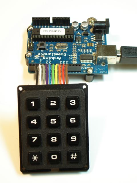
Most keypads like this are wired so it makes it straightforward to figure out what button is being pressed. With 3 columns and 4 rows of buttons, you only need 7 wires. Typically all the buttons in a column are connected together with the same wire, and all the buttons in a row are connected together with the same wire. To determine which button is pressed, you apply a voltage to the wire attached to a column and then check the wires attached to each row to see if current is flowing through any of them. If so, then the switch for a particular button is closed (button pressed). Then you proceed to the next column and try each row again, etc. Not rocket science — just scanning a bunch of switches to see which one is closed. In fact, there is a keypad library in the Arduino Playground that makes it easy to do this.
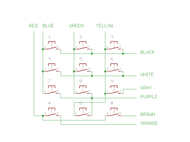
Well, the keypad I bought here has 10 wires instead of 7, and it’s wired in a really goofy way. I’m not sure if this is common, but I thought keypads were generally wired as described above. Here’s the schematic that shows how this one is actually wired:
Regardless, here is Arduino code that I used to scan this keypad. You can do something similar if you have a keypad that is not wired in a straightforward way.
// Pins
#define BLACK 2
#define WHITE 3
#define GRAY 4
#define PURPLE 5
#define BLUE 6
#define GREEN 7
#define YELLOW 8
#define ORANGE 9
#define RED 10
#define BROWN 11

#define STAR 10
#define POUND 11


void setup() {
  Serial.begin(115200);

  // Rows
  pinMode(BLACK, INPUT);
  digitalWrite(BLACK, HIGH);  // set pull-up resistors for all inputs

  pinMode(WHITE, INPUT);
  digitalWrite(WHITE, HIGH);

  pinMode(GRAY, INPUT);
  digitalWrite(GRAY, HIGH);

  pinMode(PURPLE, INPUT);
  digitalWrite(PURPLE, HIGH);

  pinMode(ORANGE, INPUT);
  digitalWrite(ORANGE, HIGH);

  pinMode(BROWN, INPUT);
  digitalWrite(BROWN, HIGH);


  // Columns
  pinMode(BLUE, OUTPUT);
  digitalWrite(BLUE, HIGH);

  pinMode(GREEN, OUTPUT);
  digitalWrite(GREEN, HIGH);

  pinMode(YELLOW, OUTPUT);
  digitalWrite(YELLOW, HIGH);

  pinMode(RED, OUTPUT);
  digitalWrite(RED, HIGH);

}

void loop() {
  int key = scanKeypad();

  if (key != -1) {
    if (key == STAR) {
      Serial.println("*");
    } else {
      if (key == POUND) {
        Serial.println("#");
      } else {
          Serial.println(key);
      }
    }
  }
}

int scanKeypad() {
  int key = -1;

  // Pull the first column low, then check each of the rows to see if a
  // button is pressed.
  digitalWrite(BLUE, LOW);
  if (digitalRead(BLACK) == LOW) {
    key = 1;
  }
  if (digitalRead(WHITE) == LOW) {
    key = 4;
  }
  if (digitalRead(PURPLE) == LOW) {
    key = 7;
  }
  digitalWrite(BLUE, HIGH);

  // Moving on to the second column....
  digitalWrite(GREEN, LOW);
  if (digitalRead(BLACK) == LOW) {
    key = 2;
  }
  if (digitalRead(WHITE) == LOW) {
    key = 5;
  }
  if (digitalRead(PURPLE) == LOW) {
    key = 8;
  }
  digitalWrite(GREEN, HIGH);

  // Third "column".  Note that the 0 key is wired to this column even though
  // the 0 is really in the second column.
  digitalWrite(YELLOW, LOW);
  if (digitalRead(BLACK) == LOW) {
    key = 3;
  }
  if (digitalRead(WHITE) == LOW) {
    key = 6;
  }
  if (digitalRead(GRAY) == LOW) {
    key = 9;
  }
  if (digitalRead(PURPLE) == LOW) {
    key = 0;
  }
  digitalWrite(YELLOW, HIGH);

  // Last "column" is not really it's own column.  Only wired to * and #
  digitalWrite(RED, LOW);
  if (digitalRead(ORANGE) == LOW) {
    key = STAR;
  }
  if (digitalRead(BROWN) == LOW) {
    key = POUND;
  }
  digitalWrite(RED, HIGH);

  return key;
}


I would suggest that this keypad is wired like this to allow for easy coding of emergency codes (the 9 key on its own) and easy reading of the * and # key so that you could use them for a power switch or similar.
Many keypad locks require you to press either * or # before the numbers, maybe this is why.
I can see some uses for it. It is still rather weird though.
Just another quick comment, why is this comment box text so darn small? My monitor is not a particually high res but this is really small text (oh the wonders of Ctrl+ to make it bigger for me)
um, i have an arduino uno and i was wondering if the wiring would be the same. i have the exact same keypad,and cant figure out how to wire it. please help!
@Sara, The article above includes a schematic for the keypad and the code for accessing it. I’m not sure what else you need!