Driving Multiple Digit Shields from One Arduino
Difficulty Level = 2 [What’s this?]
The Digit Shield is a very easy-to-use Arduino shield that provides a digital readout for your Arduino projects. Some example projects are here.
One of my customers asked me about driving multiple Digit Shields from one Arduino. I had never thought of that, but the customer had the idea of using a single Arduino to display the X,Y,Z positions of a CNC router. I thought this was an intriguing idea, and with a little bit of experimentation and modification to the Digit Shield library, I was able to very easily accomplish this.
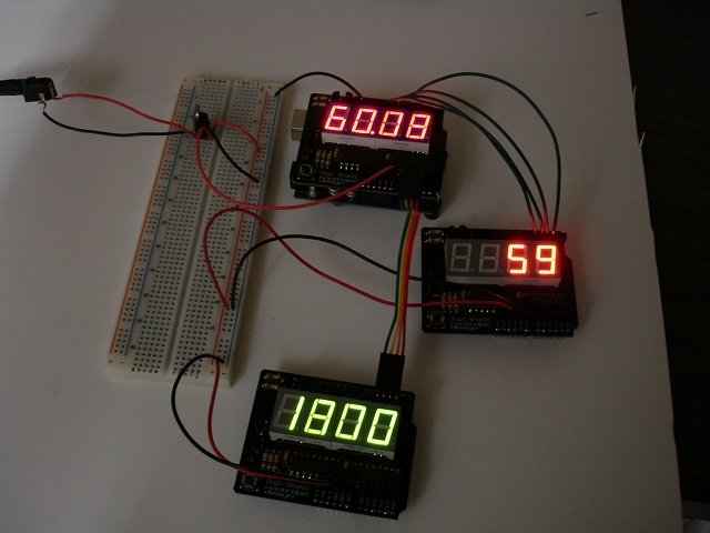
When a Digit Shield is on top of an Arduino, the pins used to control the shield are 2, 3, 4, and 5. In the picture above, this shield is displaying value “60.08”. If we connect another shield, we obviously have to use different Arduino pins to drive it. The second shield in the picture above (the one displaying “59”) is connected to Arduino pins 6, 7, 8, and 9. Of course, the wires still connect to pins 2, 3, 4, and 5 on the shield itself.
The 3rd shield in the picture displaying “1800” has its pins 2, 3, 4, and 5 connected to Arduino pins A3, A2, A1, and A0 respectively. In the code, analog pins are used as digital pins by referring to them as 17, 16, 15, and 14.
What about the code? I added a constructor for DigitShieldClass to the library so you can create new objects to represent the additional shields. The shield on the Arduino is still referenced as “DigitShield”, but the additional ones are referenced as “digitShield2” and “digitShield3”. Here’s how the shields are declared and initialized.
// Create a second Digit Shield connected to Arduino pins 6,7,8,9
// Connected to pins 2,3,4,5 on the shield, respectively.
DigitShieldClass digitShield2(6, 7, 8, 9);

// Create a third Digit Shield connected to Arduino pins 17,16,15,14 (A3,A2,A1,A0)
// Connected to pins 2,3,4,5 on the shield, respectively.
DigitShieldClass digitShield3(17, 16, 15, 14);

void setup() {
  // The static variable DigitShield refers to the default
  // Digit Shield that is directly on top of the Arduino
  DigitShield.begin();
  DigitShield.setPrecision(2);

  // Initialize the other two shields
  digitShield2.begin();
  digitShield3.begin();

  // set all values to 0
  DigitShield.setValue(0);
  digitShield2.setValue(0);
  digitShield3.setValue(0);
}
The full code example is called “MultiShieldExample” and is included in the Digit Shield library.
Also note that I’m providing power to the off-Arduino shields with a 7805 voltage regulator. The Arduino’s voltage regulator can deliver quite a bit of power, but it got rather warm when driving all these LEDs. So, in the picture above, there’s a 7805 which provides 5V to the 5V pins on the off-Arduino shields. Also make sure you connect all the grounds together.
Overlay GPS Data on Video
Difficulty Level = 7 [What’s this?]
Several people in the FPV RC world (that’s First Person View Remote Control for the uninitiated) have contacted me about the possibility of using a Video Experimenter shield as an OSD solution (on screen display). People who fly RC planes and helicopters are increasingly using on-board video cameras to provide a first-person view of the flight, and they like to overlay GPS data onto the video image. Flying radio controlled drones has become a huge hobby (just look how big the DIYDrones and RCGroups communities are!).
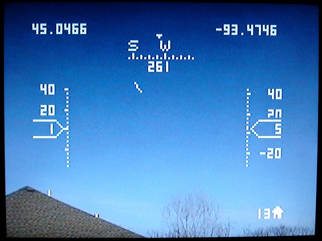
I don’t have any RC vehicles, so I’m really on the outside looking in, but I thought I’d experiment to see how useful a Video Experimenter might be in overlaying data onto a video feed. I wrote a simple Arduino program that reads GPS data from the Arduino’s serial RX pin and overlays a heads-up display onto the video input. I think it turned out pretty nice:
All relevant info is displayed: current latitude/longitude, compass heading, speed (left), altitude (right), and distance home (meters) in the lower right. There’s also a home arrow in the center of the screen pointing toward the hard-coded home location. Note that the ground elevation is also hard coded in the Arduino program so we can calculate altitude.
Circuit Setup
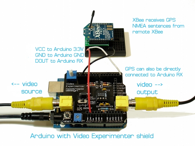
I think there are two ways that a FPV solution could use this approach. If the vehicle is transmitting video and also transmitting GPS telemetry via an XBee radio, then the GPS data can be overlayed onto the video at the ground station. I had to configure the XBee radios to use the same baud rate as my GPS (4800bps).
OR the Arduino and Video Experimenter shield could be onboard the vehicle itself. This way the GPS data is overlayed onto the video before the video is transmitted. In this case, the GPS module is connected directly to the Arduino RX pin, and there’s no XBee radios involved. An Arduino+Video Experimenter shield weigh 2 ounces or 57 grams (I knew you were going to ask that).
I need to be clear that this overlay software can’t run on your ArduPilot hardware. Processing video in an Arduino environment requires nearly all of the ATmega’s SRAM, so there’s no way that this is going to run on the same hardware as your autopilot code.
Again, I’m not in the FPV RC community and don’t have a plane, so I’m not entirely sure how feasible all this is. But a number of RC hobbyists have asked about the Video Experimenter and were enthusiastic about the possibilities. Comments are very welcome!
GPS Configuration
My EM-406 GPS module is configured to only output RMC and GGA sentences, and they are output once per second, so the display only updates at that frequency. It was important to limit the output to only the RMC and GGA sentences, because when using the Arduino video library (TVout), serial communication is accomplished by polling, and it can’t handle data too quickly. To limit the output to RMC and GGA sentences, I wrote these commands to the GPS RX line, with each line followed by a CR and LF character. The Arduino serial terminal works fine for this. Don’t write the comments, of course.
# enable RMC, output 1Hz:
$PSRF103,04,00,01,01*21

# enable GGA, output 1Hz:
$PSRF103,00,00,01,01*25

#disable GLL
$PSRF103,01,00,00,01*25

#disable GSA
$PSRF103,02,00,00,01*26

#disable GSV
$PSRF103,03,00,00,01*27

#desiable VTG
$PSRF103,05,00,00,01*21
If you have a MediaTek GPS module, I believe the correct command to disable all sentences except for RMC and GGA would be this:
$PGCMD,16,1,0,0,0,1*6A
I don’t know how fast of a data feed that the Arduino overlay code can handle, so some experimentation would be in order.
Download
Download the Arduino code OverlayGPS.zip. The awesome TinyGPS library is also required, so install it in your Arduino libraries folder. You also must use the TVout library for Video Experimenter that is required for Video Experimenter projects.
Decoding Closed Captioning Data
Difficulty Level = 8 [What’s this?]
How Does Closed Captioning Work?
Closed captioning is the technology used to embed text or other information in an NTSC television broadcast (North America, Japan, some of South America). It is typically a transcription of the broadcast audio for the benefit of hearing impaired viewers. No doubt, you’ve all seen closed captions displayed on a TV, but how does it work? This project will explain how closed captioning technology works and then show you how you can decode and display the data using your Arduino and a Video Experimenter shield. There a lot to learn here, so be patient! First, you can take a look at a video showing this capability, then keep reading to learn how it works.
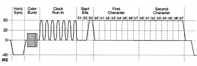
The data that your TV displays is embedded in the broadcast itself in a special format, and in a special location of the video image. When you activate the closed captioning feature on your TV, your TV decodes the information and displays it on the screen. Whether you are displaying it or not, the data is in the broadcast encoded on line 21 of the video frame. This is defined by the standard EIA-608. Here is what the line 21 signal looks like:
This shows the voltage of a composite video signal for line 21. The horizontal sync and color burst are just like any other video line, but the section called “clock run-in” is a special sinusoidal wave that allows the TV to synchronize with the closed captioning data which is about to start. The 7-peak run-in is followed by 3 start bits with values of 001. You can see how the voltage rises for the third bit S3. The next 16 bits represent two 8-bit characters of text. That’s right, there are only two characters per video frame, but at 30 frames per second, there is enough bandwidth for closed captions. The last bit of each byte b7 is an odd parity bit. Parity bits are an error detection mechanism. That is, this bit is either on or off in order to keep the total bits in the byte at an odd number. So, if bits b0-b6 have 4 bits on, then the parity bit is on to achieve an odd number of bits (5).
Capturing and Decoding the Data
So, how do we capture and decode this data using the Video Experimenter? We need to use the TVout library for Video Experimenter used with all Video Experimenter projects. The code for this project is in the example “ClosedCaptions” in the TVout/examples folder. You may already know from other Video Experimenter projects that we can capture a video image in the TVout frame buffer. For this project, we just want to capture the line 21 data so we can decode it. This is accomplished with the API method: tv.setDataCapture(int line, int dataCaptureStart, char *ccdata) where ‘line’ is the TVout scan line to capture, ‘dataCaptureStart’ is the number of clock cycles on that line to wait before starting to capture, and ‘ccdata’ is a buffer to store the bits in. Typically, we do something like this:
  unsigned char ccdata[16]; // 128 pixels wide is 16 bytes
  ...
  tv.setDataCapture(13, 310, ccdata);
Even though the data is on line 21, I have found it to be on line 13 or 14 as far as TVout is concerned. The value of 310 for dataCaptureStart is the value I have found to work best in order to fit both characters of data in the width of the TVout frame buffer. This will make more sense later when we visually look at the pixels captured. It may take a while to “find” the data by trying different lines and different values for dataCaptureStart to get the right alignment. Just try different values. I have also needed to adjust the small potentiometer near the reset button upward a bit. A resistance of around 710K was required instead of the standard 680K required by the LM1881 chip on the Video Experimenter. You’ll know when you’ve found the data when you see a data line like in the images below. Sometimes you might find data that is not closed captions, but information about the program, like the title, etc. This is called XDS or Extended Data Services. This can be interesting information to decode also!
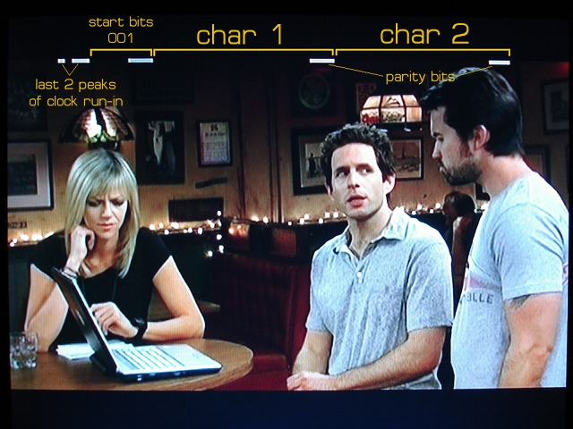
Once we tell enhanced TVout where to find the data, the buffer ccdata will always contain the pixels of the specified line of the current frame. If we display the captured pixels on the screen we can visually see how it matches up with the line 21 waveform. To produce the picture below, I copied the contents of ccdata to the first line of the TVout frame buffer so we can see the data with our eyes. The data appears as white pixels at the top of the image. It isn’t necessary to display it on the screen in order to decode it and write it to the Serial port. But it makes it easier to find the data visually and see what’s going on.
On the left side we can see the last 2 peaks of the clock run in sine wave. Then we clearly see the start bits 001. Each bit is about 5 or 6 pixels wide. Then there are 7 zero bits (pixels off) and the parity bit (on). When this picture was taken, no dialog was being spoken, so the characters are all zero bits except for the parity bit. When text data is being broadcast, the bits flash very quickly:
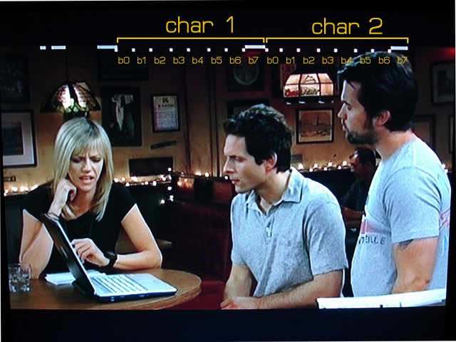
Now that we have found the data in the broadcast, and can display it for inspection, we need to decode this 128-bit wide array of pixels into the two text characters. To do that, we need to note where each bit of the characters starts. Each bit is 5 or 6 pixels wide. The next step I took in my program was to define an array of bit positions that describe the starting pixel of each bit:
byte bpos[][8]={{26, 32, 38, 45, 51, 58, 64, 70}, {78, 83, 89, 96, 102, 109, 115, 121}};
These are the bit positions for the two bytes in the data line. By displaying these bit positions just below the data line, we can adjust them if needed by trial and error. Here’s an image with the bit positions displayed below the data line. Since each data bit is nice and wide, they don’t have to line up perfectly to get reliable decoding. These positions have worked well for me for a variety of video sources.
OK, we are almost done. Now that we have found the closed caption data line, and have established the starting points for each bit, we can easily decode the bits into characters and write them to the serial port for display on a computer. We can also just print them to the screen if we want. I have taken care of all this code for you, and it is all in the example called “ClosedCaptions” in the TVout library for Video Experimenter.
If you have problems finding the data, try different lines for the data (13 or 14), different values for dataCaptureStart, and adjust both potentiometers on the Video Experimenter. Try slowly turning the small pot near the reset button clockwise. If you are patient, you’ll find the data and decode it!
Other project ideas
- Instead of writing the data to the serial port, write it to the screen itself with tv.print(s)
- Search for keywords in a closed captions and light an LED when the word is found.
Arduino Computer Vision
Difficulty Level = 5 [What’s this?]
The Video Experimenter shield can give your Arduino the gift of sight. In the Video Frame Capture project, I showed how to capture images from a composite video source and display them on a TV. We can take this concept further by processing the contents of the captured image to implement object tracking and edge detection.
The setup is the same as when capturing video frames: a video source like a camera is connected to the video input. The output select switch is set to “overlay”, and sync select jumper set to “video input”. Set the analog threshold potentiometer to the lowest setting.
Object Tracking
Here is an Arduino sketch that captures a video frame and then computes the bounding box of the brightest region in the image.
This project is the example “ObjectTracking” in the TVout library for Video Experimenter. The code first calls tv.capture() to capture a frame. Then it computes a simple bounding box for the brightest spot in the image. After computing the location of the brightest area, a box is drawn and the coordinates of the box are printed to the TVout frame buffer. Finally, tv.resume() is called to resume the output and display the box and coordinates on the screen.
Keep in mind that there is no need to display any output at all — we just do this so we can see what’s going on. If you have a robot with a camera on it, you can detect/track objects with Arduino code, and the output of the Video Experimenter doesn’t need to be connected to anything (although the analog threshold potentiometer would probably need some adjustment).
If you use a television with the PAL standard (that is, you are not in North America), change tv.begin(NTSC, W, H) to tv.begin(PAL, W, H).
#include <TVout.h>
#include <fontALL.h>
#define W 128
#define H 96

TVout tv;
unsigned char x, y;
unsigned char c;
unsigned char minX, minY, maxX, maxY;
char s[32];


void setup()  {
  tv.begin(NTSC, W, H);
  initOverlay();
  initInputProcessing();

  tv.select_font(font4x6);
  tv.fill(0);
}


void initOverlay() {
  TCCR1A = 0;
  // Enable timer1.  ICES0 is set to 0 for falling edge detection on input capture pin.
  TCCR1B = _BV(CS10);

  // Enable input capture interrupt
  TIMSK1 |= _BV(ICIE1);

  // Enable external interrupt INT0 on pin 2 with falling edge.
  EIMSK = _BV(INT0);
  EICRA = _BV(ISC01);
}

void initInputProcessing() {
  // Analog Comparator setup
  ADCSRA &= ~_BV(ADEN); // disable ADC
  ADCSRB |= _BV(ACME); // enable ADC multiplexer
  ADMUX &= ~_BV(MUX0);  // select A2 for use as AIN1 (negative voltage of comparator)
  ADMUX |= _BV(MUX1);
  ADMUX &= ~_BV(MUX2);
  ACSR &= ~_BV(ACIE);  // disable analog comparator interrupts
  ACSR &= ~_BV(ACIC);  // disable analog comparator input capture
}

// Required
ISR(INT0_vect) {
  display.scanLine = 0;
}


void loop() {
  tv.capture();

  // uncomment if tracking dark objects
  //tv.fill(INVERT);

  // compute bounding box
  minX = W;
  minY = H;
  maxX = 0;
  maxY = 0;
  boolean found = 0;
  for (int y = 0; y < H; y++) {
    for (int x = 0; x < W; x++) {
      c = tv.get_pixel(x, y);
      if (c == 1) {
        found = true;
        if (x < minX) {
          minX = x;
        }
        if (x > maxX) {
          maxX = x;
        }
        if (y < minY) {
          minY = y;
        }
        if (y > maxY) {
          maxY = y;
        }
      }
    }
  }

  // draw bounding box
  tv.fill(0);
  if (found) {
    tv.draw_line(minX, minY, maxX, minY, 1);
    tv.draw_line(minX, minY, minX, maxY, 1);
    tv.draw_line(maxX, minY, maxX, maxY, 1);
    tv.draw_line(minX, maxY, maxX, maxY, 1);
    sprintf(s, "%d, %d", ((maxX + minX) / 2), ((maxY + minY) / 2));
    tv.print(0, 0, s);
  } else {
    tv.print(0, 0, "not found");
  }


  tv.resume();
  tv.delay_frame(5);
}
What if you want to find the darkest area in an image instead of the brightest? That’s easy — just invert the captured image before processing it. Simply call tv.fill(INVERT).
Edge Detection
The Arduino is powerful enough to do more sophisticated image processing. The following sketch captures a frame then performs an edge detection algorithm on the image. The result is the outline of the brightest (or darkest) parts of the image. This could be useful in object recognition applications or
robotics. The algorithm is quite simple, especially with a monochrome image, and is described in this survey of edge detection algorithms as “Local Threshold and Boolean Function Based Edge Detection”.
This project is the example “EdgeDetection” in the TVout library for Video Experimenter.
Video Frame Capture using the Video Experimenter Shield
Difficulty Level = 3 [What’s this?]
In addition to overlaying text and graphics onto a video signal, the Video Experimenter shield can also be used to capture image data from a video source and store it in the Arduino’s SRAM memory. The image data can be displayed to a TV screen and can be overlayed onto the original video signal.
Believe it or not, the main loop of the program is this simple:
void loop() {
  tv.capture();
  tv.resume();
  tv.delay_frame(5);
}
NOTE: On versions of Arduino greater than 1.6, you may need to add a 1ms delay at the end of loop. Just the line “delay(1);”.
For this project, we connect a video camera to the input of the Video Experimenter shield. The output select switch is set to “overlay” and the sync select jumper is set to “video input”. The video output is connected to an ordinary TV. When performing this experiment, turn the analog threshold potentiometer to the lowest value to start, then adjust it to select different brightness thresholds when capturing images.
By moving the output select switch to “sync only”, the original video source is not included in the output, only the captured monochrome image. You will need to adjust the threshold potentiometer (the one with the long shaft) to a higher value when the output switch is in this position. Experiment!
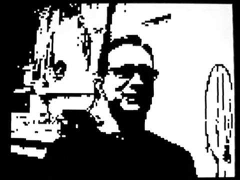
In the VideoFrameCapture.ino sketch below, we capture the image in memory by calling tv.capture(). When this method returns, a monochrome image is stored in the TVout frame buffer. The contents of the frame buffer are not displayed until we call tv.resume(). This project is the example “VideoFrameCapture” in the TVout library for Video Experimenter.
Here is the Arduino code. If you use a television with the PAL standard (that is, you are not in North America), change tv.begin(NTSC, W, H) to tv.begin(PAL, W, H).
#include <TVout.h>
#include <fontALL.h>
#define W 128
#define H 96

TVout tv;
unsigned char x,y;
char s[32];


void setup()  {
  tv.begin(NTSC, W, H);
  initOverlay();
  initInputProcessing();

  tv.select_font(font4x6);
  tv.fill(0);
}


void initOverlay() {
  TCCR1A = 0;
  // Enable timer1.  ICES0 is set to 0 for falling edge detection on input capture pin.
  TCCR1B = _BV(CS10);

  // Enable input capture interrupt
  TIMSK1 |= _BV(ICIE1);

  // Enable external interrupt INT0 on pin 2 with falling edge.
  EIMSK = _BV(INT0);
  EICRA = _BV(ISC01);
}

void initInputProcessing() {
  // Analog Comparator setup
  ADCSRA &= ~_BV(ADEN); // disable ADC
  ADCSRB |= _BV(ACME); // enable ADC multiplexer
  ADMUX &= ~_BV(MUX0);  // select A2 for use as AIN1 (negative voltage of comparator)
  ADMUX |= _BV(MUX1);
  ADMUX &= ~_BV(MUX2);
  ACSR &= ~_BV(ACIE);  // disable analog comparator interrupts
  ACSR &= ~_BV(ACIC);  // disable analog comparator input capture
}

ISR(INT0_vect) {
  display.scanLine = 0;
}

void loop() {
  tv.capture();
  //tv.fill(INVERT);
  tv.resume();
  tv.delay_frame(5);
  delay(1);
}
