
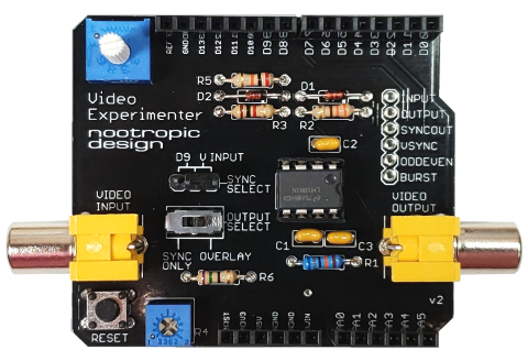
The Video Experimenter shield is an Arduino shield that lets you do all kinds of experiments with video.
- Overlay text and graphics onto a video signal from a camera, DVR, DVD player, VCR or any other source of composite video.
- Capture low-res video image frames for display or video processing. Give your Arduino the gift of sight!
- Perform object detection for computer vision projects.
- Decode NTSC closed captioning or XDS (extended data services) data embedded in television broadcasts.
- Works with NTSC (North America, parts of South America and Asia) or PAL (most of the rest of the world) television standards. For more info on what TV standards see the map here and this list of countries and their standards.
- Uses digital pins 2, 6, 7, 8, and optionally 9. Uses analog pin 2.
- Designed for Arduino Uno, Duemilanove and equivalents. Does not work on Leonardo or Mega (more info here).
All of these capabilities are demonstrated on the projects page.
Board Features
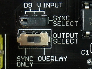
A small switch lets you control whether the original input video signal is included in the output. Here’s how these settings affect the output:
| output select=overlay | output select=sync only | |
| sync select= video input |
contents of TVout buffer overlayed onto input signal | only contents TVout buffer displayed |
| sync select= D9 |
invalid setting | contents of TVout buffer displayed (no video input present) |
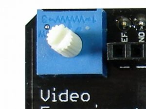
A potentiometer with a long shaft lets you easily adjust the analog threshold voltage used by the Arduino analog comparator. This allows you to adjust the brightness threshold value when capturing video frames.
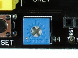
The small potentiometer R4 is used to adjust the RSET value for the LM1881 sync separator chip. Normally, keep this at its lowest setting, but if you experience vertical jumpiness, you can increase it a bit. This adjustment is also useful for capturing closed captioning data from a broadcast.
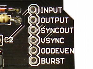
All of the outputs of the LM1881 chip are broken out for easy access (burst, odd/even, vertical sync, horizontal sync). You can also access the video output signal on pin “output” or feed in a video input on the “input” pin (for example, if you have a small CMOS camera with wires instead of an RCA plug).
Enhanced TVout Library
The Video Experimenter requires using an enhanced version of the Arduino TVout library. The enhancements allow the capture of video signal information in the TVout frame buffer so that primitive frame capture can be accomplished. The enhancements also facilitate the retrieval of embedded data streams from broadcasts.
Installation:
The enhanced version of TVout has 3 folders to install in your Arduino libraries folder. The structure should look like this:
libraries
    |
    + TVout
    + TVoutfonts
    + pollserial
API summary
capture() : captures a monochrome video frame in the frame buffer’s memory. Stops display of frame after capture to allow processing of the data if required (for example in computer vision projects).
resume() : resumes display of the TVout frame buffer after performing a capture.
setDataCapture(int line, int dataCaptureStart, char *databuf) : set the line and pixel start for data capture into the provided array databuf
Arduino sketches that use the enhanced TVout library with the Video Experimenter shield also must perform some initialization of the ATmega registers. In the project examples you will find methods like initOverlay() and initInputProcessing() to enable certain features of the chip. All Video Experimenter projects also have an interrupt service routine (ISR) for the input capture on pin 2. This is required in your program and the examples demonstrate this.