Arduino Audio Hacker Realtime Voice Changer
Here’s another fun but simple project using the Audio Hacker shield for Arduino. This is a realtime voice changer, which is an improvement upon the original voice changer example I provided with the Audio Hacker library.
This project uses a technique called granular synthesis to change the pitch of the input. Granular synthesis is rather complex, but it involves dividing the sample up into small fragments called “grains”. When playing back a sample, if we want the pitch higher, we play the grain at a higher speed, but we play it over and over again until it takes the same amount of time as the grain played at original speed. Likewise, to lower pitch, we play each grain at a slower speed, but move onto the next grain sooner so that the overall sample has the same duration.
This realtime voice changer only lowers pitch. Raising pitch would require a lag to record something and play snippits of it faster. Lowering the pitch is accomplished by recording the input and then simultaneously playing it slower. That is, the “play head” moves slower than the “record head”. Occasionally, the play head needs to skip ahead over some of the input and catch up to the record head. This way, the playback takes the same amount of time as the recording, making it seem realtime. It is realtime, we are just playing only part of what was input (slowly) and skipping the rest so that the overall time is the same.
The example is in the Audio Hacker Library examples folder so you can load it into the Arduino IDE with
File->Examples->Audio Hacker->RealtimeVoiceChanger
As always, get the Audio Hacker library from GitHub: https://github.com/nootropicdesign/audio-hacker
Arduino Audio Hacker Realtime Reverser
Here’s a fun project using the Audio Hacker shield for Arduino – a realtime audio reverser! This program records the audio input to the Audio Hacker’s memory but plays it back in reverse. The “play head” jumps ahead a bit, then plays recorded audio backwards, then jumps ahead to the next snippet, plays it backward, and so on. There is a bit of lag between the input signal and reversed output, but this is unavoidable: we have to record something before playing it backward. There’s no way to play something backward in perfect realtime. This audio snippets are about a half-second long, so the lag is pretty small.
It’s great to hook up to a TV signal and just reverse all the audio. Using this effect, spoken English sounds like Russian to me!
The example is in the Audio Hacker Library examples folder so you can load it into the Arduino IDE with
File->Examples->Audio Hacker->RealtimeReverser
As always, get the Audio Hacker library from GitHub: https://github.com/nootropicdesign/audio-hacker
Arduino Shield for CAT M1 and NB-IoT Modems
LTE CAT M1 (sometimes called LTE-M) and NB-IoT are both exciting new cellular technologies targeting IoT applications. While there are many modems being built with this new technology, there are not many choices for hobbyists. There are a few Arduino shields and breakout boards based on the SIMCOM SIM7000 modem, and a few with u-blox SARA modems.
Nimbelink is a cellular technology provider that takes the unique approach of offering a variety of different modems as interchangeable modules. No matter what the actual cellular modem is, the 20-pin Nimbelink Skywire modules with the familiar “XBEE” footprint all have the same pinout and electrical characteristics. The interchangeable nature of these modem modules allows product designers to future-proof their products, allowing new modules to be plugged in later. Another huge benefit is that the Nimbelink modules are already certified on their respective cellular networks (Verizon, AT&T, etc.) so you don’t have to.
Nimbelink has a development kit for use by product developers, but it’s rather expensive. I wanted to try out a Nimbelink CAT M1 modem without the dev kit, and since there are so many hobbyists using Arduinos out there, I wanted to provide a nice Arduino library for the modem. I chose the Nimbelink module based on the Sequans Monarch CAT M1 modem and got to work designing an Arduino shield to hold it.
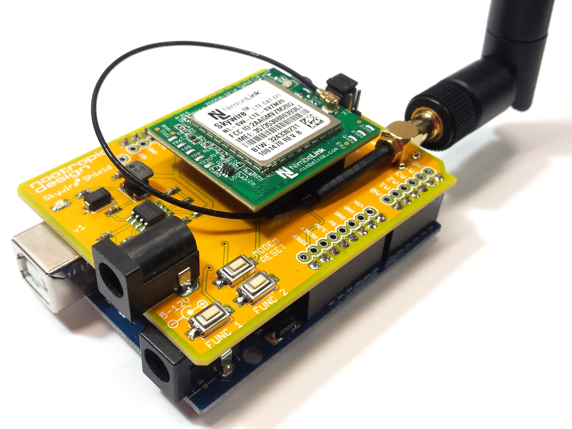
Skywire Shield with Nimbelink Skywire module with Sequans Monarch CAT M1 modem
Hardware Design
The shield is quite simple, and really just provides an appropriate switch-mode power supply for the modem. The input power for the shield can be 5-12V, and provides a stable 3.8V at up to 1.7A to the modem. I used a TI TPS5402 for this. Jumper settings allow you to connect the modem’s UART to the Arduino hardware UART on pins 0 and 1 or to software serial on digital pins 2 and 3. I typically use software serial at 19200 so that I can use the Arduino serial interface for debugging. The buttons labeled “Func 1” and “Func 2” are connected to digital pins 4 and 5.
Software Interface
What about actually using the modem in software? Every modem has its own AT command set, and although there are similarities, a developer must know the details of the modem they are using. Luckily, the excellent TinyGSM Arduino library provides an Arduino Client interface for a variety of underlying modems. The Arduino Client interface is widely used by networking libraries to abstract away the underlying hardware. That is, when you code to the Client API, it doesn’t matter if the hardware underneath is an Ethernet shield, an ESP8266, a cellular modem, or whatever. Examples of libraries that code to this interface and therefore work with many kinds of hardware are ArduinoHttpClient for web clients and PubSubClient for MQTT clients. Even HTTPS and MQTT over TLS work! Security is important.
TinyGSM did not have an implementation for the Sequans modem, so I wrote one. It’s in my forked repo of TinyGSM (it has not been merged into the parent yet). To use the TinyGSM examples with the Nimbelink module with a Sequans modem, simply add this to your source code:
#define TINY_GSM_MODEM_SEQUANS_MONARCH
I also bought a Nimbelink module with the Quectel BG96 CAT M1 and NB-IoT modem on it. Luckily, TinyGSM already has an Client interface implementation for this modem. After plugging it into my shield and simply changing my HTTP and MQTT test clients to use this modem, everything just worked! That is, I was able to change the modem to a different manufacturer (and completely different AT command set) and make my code work with a one line change:
#define TINY_GSM_MODEM_BG96
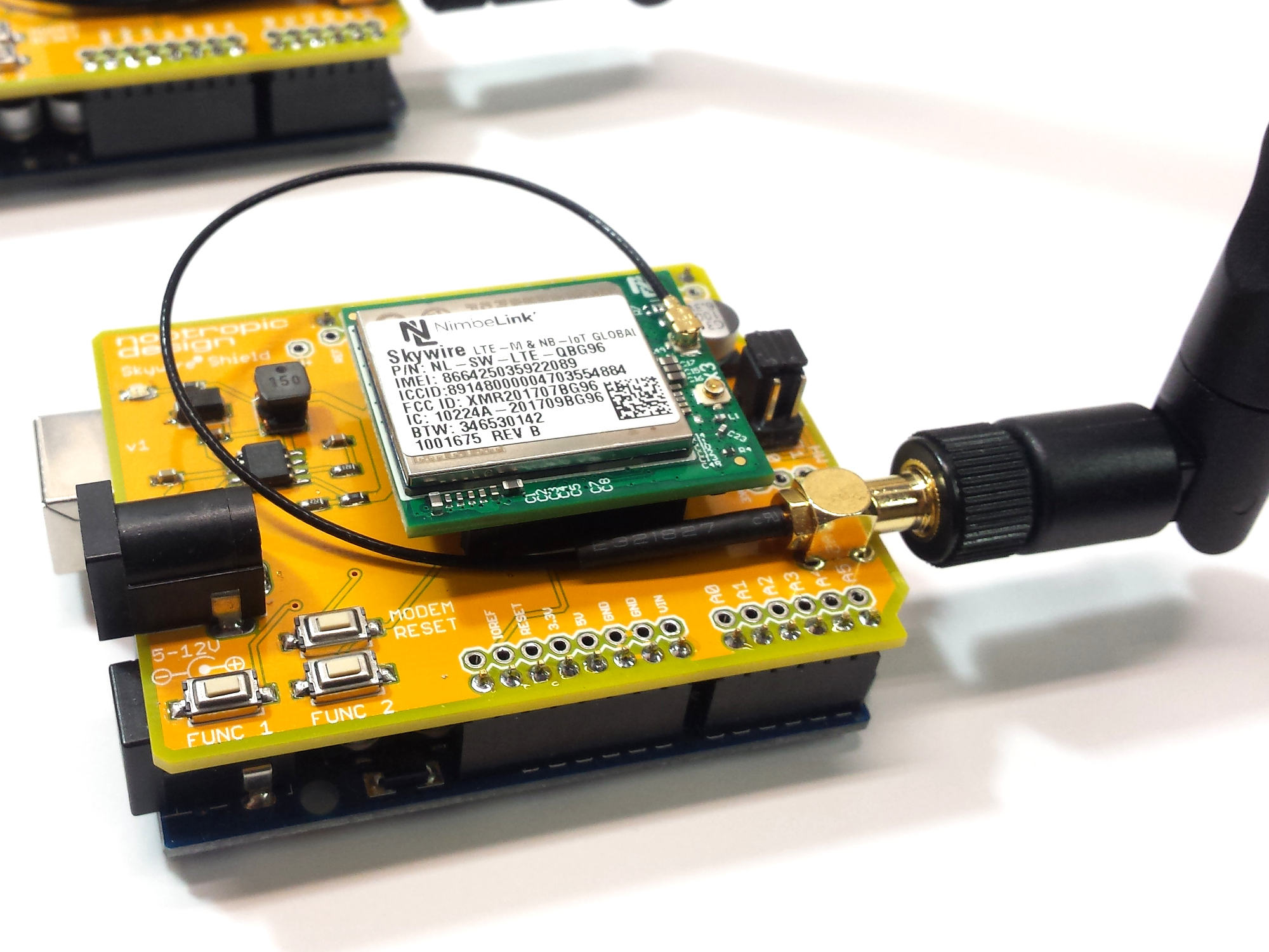
Skywire Shield with Nimbelink Skywire module with Quectel BG96 CAT M1/NB-IoT modem
So the lesson here is that with thoughtful design of software and hardware abstractions, one can achieve a lot of flexibility.
- the Arduino Client interface defines a standard software API for network clients so that an implementation for any hardware can be written and expose its functions through this same interface
- useful libraries like ArduinoHttpClient and PubSubClient code to this interface so that HTTP and MQTT are easily used with lots of hardware
- and finally, Nimbelink has defined a standard Skywire module pinout so that it’s easy to swap out the hardware
This is all getting pretty easy, right?! I hope you agree.
I haven’t decided if I’ll make this shield available as a product because there has to be some real demand for that to be worth it. Let me know if you are interested in an easy way to get started with modern cellular technology using Nimbelink modules.
Schematic and board design files at GitHub: skywire-cat-m1-modem-shield
Arduino library for controlling the Sequans Monarch and Quectel BG96 modems: TinyGSM
Building an IVR with Twilio and Node-RED
Node-RED Library page: node-red-contrib-twilio-ivr
Project source code at GitHub: node-red-contrib-twilio-ivr

Twilio is fast becoming an important part of Internet’s communication infrastructure. What is Twilio? Twilio is a developer platform that allows you to add capabilities like voice, video, and messaging to your applications. This project uses the Twilio Programmable Voice APIs to bridge the gap between the telephone system and the Internet. It connects the mysterious, traditionally closed world of telephony with the open Internet. If you like building things on the Internet, now you can integrate with those things using the phone system, whether it be via voice calls, text messages, or even wireless devices with Twilio SIM cards. Like many API services, Twilio has a pay-as-you-go model, so I’ve been able to explore all this great functionality for very little money. In this project I will show you how you can build an IVR (Interactive Voice Response) system with Twilio and one of my favorite technologies, Node-RED. And I have a great example IVR that you can call yourself to explore!
Twilio + Node-RED = POWER!
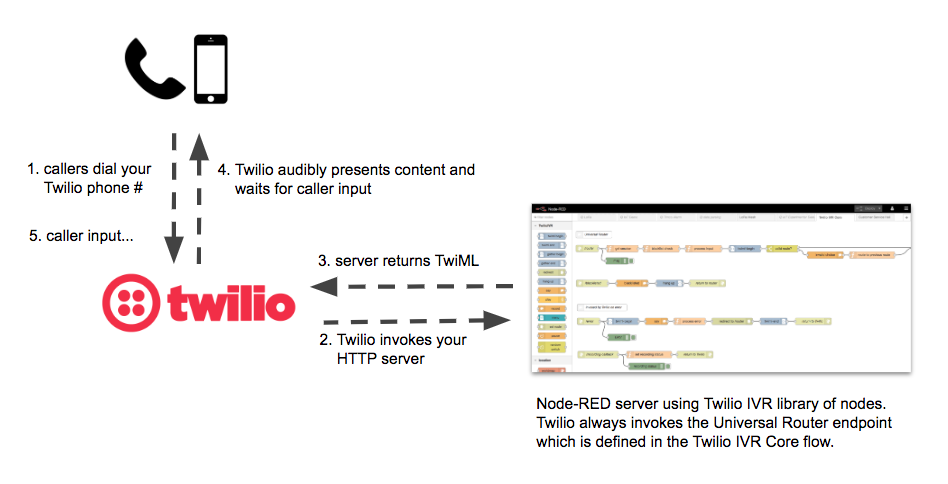
In case you don’t know what an IVR is, it’s that thing when you call a customer service phone number and are presented with a menu system that helps you (or tries to). A caller interacts with the IVR by pressing keypad numbers and speaking commands. To start using Twilio in this way, you need to buy a phone number from Twilio for your callers to call. As a developer, you present “content” to the caller by using a Twilio markup language called TwiML which instructs Twilio how to present your IVR content to whomever calls your number. It’s really just like building a web server that returns HTML that is presented by a web browser. But in this case, we build an HTTP server that returns TwiML to Twilio which audibly presents that content to the caller. The caller’s phone is the browser! Twilio handles the job of connecting telephone callers to your HTTP server.
You can build a TwiML server using any web server technology, like PHP on an Apache server, etc. I chose to use Node-RED because I use it for lots of IoT processing flows. Most importantly, by building a library of nodes specifically designed for building a Twilio IVR, I (and now you) can build sophisticated IVRs by dragging and dropping nodes into a Node-RED flow. And since Node-RED has many libraries available for integration into just about anything (including a way to invoke Twilio APIs), your IVR can integrate with databases, other servers, social media, and anything else in Internet-land. I think Node-RED is the perfect tool for creating IVR flows.
Note that Twilio has their own product like this called Twilio Studio, but I built my system before they announced their product. Besides, mine is free and I think you can build much larger and more sophisticated IVRs with my solution :)
Node-RED IVR Components
Here is an overview of the main components of an IVR built with this system. Instructions for setting all this up for your own IVR is later in this article.
Twilio IVR Library
To make all this easy, I built a library of Node-RED nodes that create TwiML for the response. Some nodes are simple and have a one-to-one correspondence with TwiML markup, like the “play” node for playing MP3 files and the “say” node for speaking text. These nodes create TwiML using the <Play> and <Say> tags. Other nodes are for higher-level IVR concepts, like the “menu” node. It lets you create a menu that is spoken to the caller and arranges for the caller input to route to the correct part of the IVR flow.
Twilio IVR Core Flow
Much of the heavy lifting of the IVR is done by a predefined Node-RED flow called Twilio IVR Core. Your IVR will use this Node-RED flow and you won’t need to change it. The main part is the Universal Router. Twilio always invokes the Universal Router HTTP endpoint (which is /router) which figures out which route to follow through the IVR based on the user’s input or routing information specified by the previously invoked route (more on this later). Routes are a key concept in the IVR. The are a particular path that the caller is on, and have names like /main-menu or /account or /agent.
Example IVR: “Customer Service Hell”
The easiest way to demonstrate the many features you can implement in an IVR was to build a great example. The Node-RED flow “Customer Service Hell” is an example that uses many features. It is designed to frustrate any caller with a maze of menu choices and frustrating interactions. You can call this IVR at (612) 999-2812. (if you are international, dial +1-612-999-2812). Please note that it costs us a small amount of money every time you call, so don’t abuse it, but by all means use it to learn and maybe get a good laugh. Here is a huge image of this Node-RED flow that you can use to follow along. Be sure to look at the route called /nightmare-hold. If you are planning on implementing a Twilio IVR, I suggest you start with this flow by import it into your Node-RED implementation (more on setup later).
Twilio Configuration
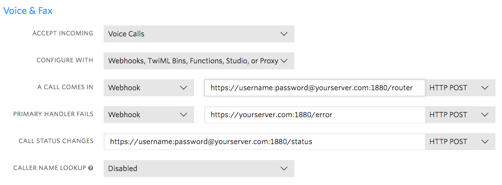
Of course you have to tell Twilio to invoke your Node-RED server: in the Twilio console, specify your server endpoints in the configuration for your Twilio phone number. Here is an example of how this should look. Node-RED can be configured to protect HTTP endpoints with username/password credentials, so you need to specify these as well. Note that the error webhook does not need the credentials (and doesn’t work if you provide them).
How It All Works
Twilio invokes the IVR over HTTP to get the TwiML response for Twilio to present to the caller. A response to the caller may request input from the caller in the form of a menu or may prompt the caller for other input like an account number or invite the caller to speak a command. The Universal Router controls the flow of a call. First, it finds the caller’s session or creates a new session if the call is new. The session keeps track of anything we want to remember since we last returned TwiML to Twilio. (It’s just like a web server session where we keep track of info before responding to the browser.)
Next, the router determines which route to invoke. For example, if a menu was presented to the caller during the last invocation, then the caller’s input must be matched to the correct route to invoke. The session automatically keeps track of any menu that was presented so that the caller’s input can be used to route correctly. For example, if the last menu told the caller to press “1” for accounting, then if they pressed “1”, we route to the /accounting route. Another important thing to note is that if a call is new, the router will invoke a route called /begin, so your IVR needs to define this route as the starting point for a new call.
Next, the router actually invokes the desired call route. Each route in the IVR begins with a Node-RED HTTP endpoint. Even though Twilio does not invoke these HTTP endpoints directly (Twilio always invokes /router), the Universal Router invokes routes via HTTP. The responsibility of a route is to return the TwiML that is to be returned to Twilio. The outer layer of TwiML (the <Response> and </Response> tags) are taken care of by the router.
Examples of Common Route Patterns
Presenting a Menu
A common pattern in an IVR is to present the caller with a menu of choices. Here is the part of the IVR that implements the /main-menu route, as well as the starting point for the whole IVR, /begin. You can see that if a call is new it says a welcome message before connecting to the /main-menu route.
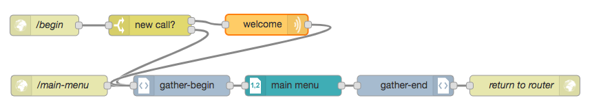
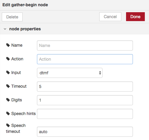
The pattern for a menu-based route is to start with a gather-begin node which tells Twilio that we want user input. See the Twilio documentation for the <Gather> TwiML element. You can configure the gather-begin node to expect DTMF (touch tones) or speech input, or both. You can also provide speech hints to help Twilio recognize speech input. For example if you are presenting a menu that allows the caller to say “representative”, then specify the string “representative” as a speech hint in the gather-begin node to help Twilio recognize the caller’s utterance.
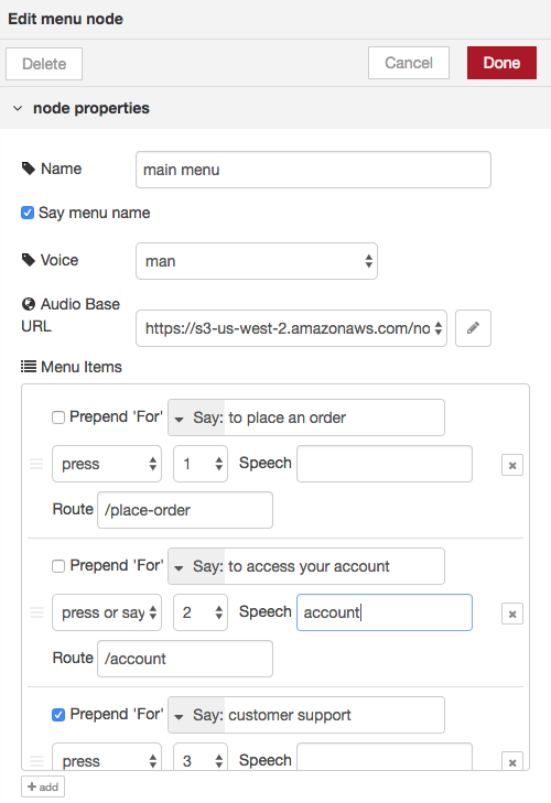
The menu node creates the TwiML that reads a menu to the caller. This node provides lots of flexibility. For each menu item, the item can be spoken (“Say”) or an audio file can be played (“Play”). The word “For” can be prepended to the name of the item if that makes sense. The caller can press a number to choose the item (“Press” option) or can press or say it (“Press or Say” option). You can also specify speech that can be used to choose the item. For example in the second item below, the caller can press 2, say “two” or say “account” to choose the item. Finally, each item specifies which route in the IVR to invoke if chosen. The Universal Router will inspect the input from the caller (whether spoken or entered) and determine the route to invoke.
Also, don’t forget to use a gather-end node before returning to the router. This adds the ending tag </Gather> to the TwiML response.
Using the set-route node
Although menus are a common pattern, not every route in an IVR presents the caller with a menu of choices. Sometimes you want to prompt the caller for input (like an account number) or prompt them to make a recording of some kind. An example of this is the /account route in the Customer Service Hell IVR. Click the image below to see this route. Note that we still need the gather-begin and gather-end nodes since we are asking for input.
![]()
Dynamically building a menu
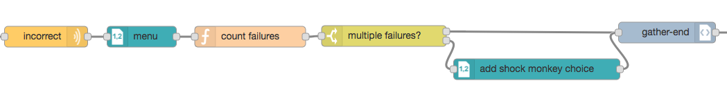
One more pattern that you may find a use for is the ability to build a menu dynamically instead of specifying it all in a single menu node. Below is a particularly insidious part of our Customer Service Hell IVR. After prompting the caller for a 4-digit PIN, it transposes the digits that they entered and tells the caller that their PIN is wrong. The IVR keeps track of the number of times the caller has failed (in the call session), and after multiple failures we add a menu choice for the caller and invite them to “shock the monkey” by pressing ‘*’. (Relax, PETA, it’s just a sound effect.) This ability to dynamically build the “content” returned to the caller is very powerful.
System Setup
Here are the steps to take if you want to actually build and IVR. I suggest you get the example “Customer Service Hell” IVR working first so you can see how everything works together.
First it is assumed you have Node-RED installed and running. If you don’t, then get started at the Node-RED website.
In your Node-RED installation, install the Twilio IVR library:
npm install node-red-contrib-twilio-ivr
Next, you’ll need to add a Node-RED flow with the Twilio IVR Core. You can get this flow from the Node-RED Library entry for this project. In Node-RED, use the Import option on the menu and import from the clipboard. Past the Twilio IVR Core content from the clipboard.
To run the Customer Service Hell IVR, create another flow in Node-RED and import from the clipboard just as you did for the Twilio IVR Core. Past the content of the IVR flow into Node-RED. This IVR relies on audio files which are retrieved by Twilio when you tell Twilio to play an audio file using a “play” or “menu” node. You can download the audio files from this link and you will need to host them on a server. You will specify the base URL of all the audio files in the configuration of your Node-RED “play” and “menu” nodes.
Don’t forget to configure your Twilio account to point your phone number at your Node-RED server (this is described earlier in the article).
Final Notes
You will need to make one change in the Twilio IVR Core flow: the Universal Route contains an HTTP node called “invoke route” which makes the HTTP call to the route endpoints. If your server is protected with a username/password you will need to specify them. You will also need to tell this node whether it needs to use SSL/TLS when connecting.

LoRaWAN Networking Part 2: Using End Devices
In part 1 of this series I showed how to set up a simple LoRaWAN gateway, and in a previous article described a simple but powerful LoRaWAN-capable end device that I designed. Now I’ll show how these devices can be used in a real LoRaWAN application.
LoRaWAN Application on The Things Network
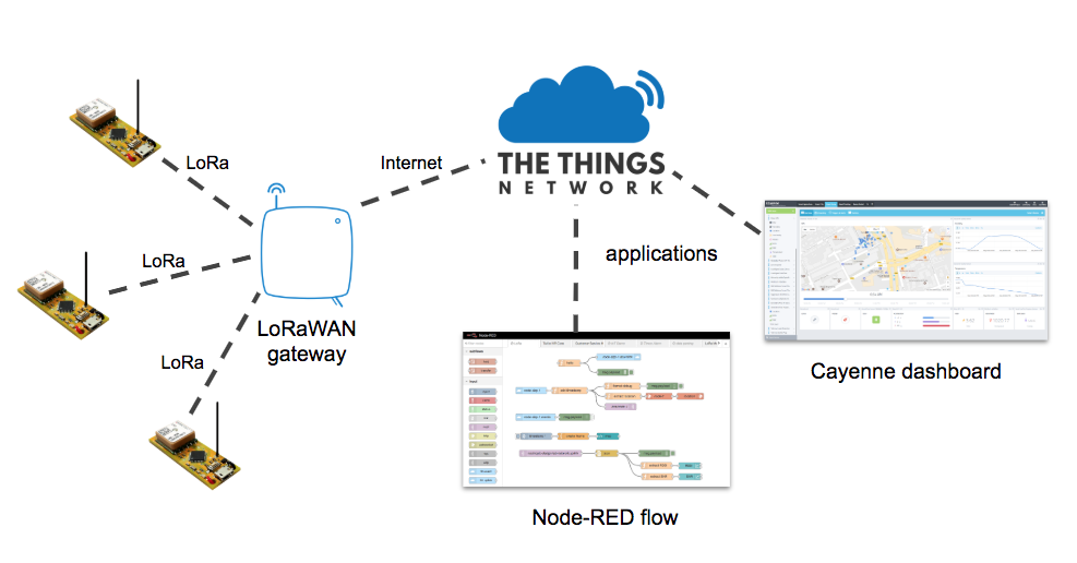
The Things Network (TTN) is the Internet infrastructure that allows us to use end devices to do something useful on the Internet. End devices (sometimes called nodes) talk to a nearby gateway, which is connected to the Things Network infrastructure. An application is anything you can imagine on the Internet that does something with the data provided by the end devices. The Things Network bridges the radio technology to Internet technology. The communication does not need to be one-way; applications can downlink data to end devices, too. A common example of an application is a Cayenne dashboard which is an easy way to visualize data from your devices. You can also read data from TTN using Node-RED, a common tool for building IoT solutions.
In part 1 I showed how a gateway is registered to TTN. To connect end device nodes, we also have to define an application in TTN, even if the real functionality of our application is implemented elsewhere on the Internet. An application has a name and a unique ID called an Application EUI. It also creates an Application Access Key that you use to integrate other services like Cayenne or Node-RED to your application. I won’t go into the integration details because there is plenty of info available about that.
After creating a TTN application, you need to add devices to the application so that your code on the devices can talk to TTN. There are 2 ways for a device to authenticate with TTN. The recommended and more secure way is called over-the-air-activation, or OTAA. This is the default mechanism when you create a device in TTN. With OTAA, a device negotiates with the network to establish a network session key and an application session key. The other mechanism is activation-by-personalization, or ABP. With ABP, the keys needed to communicate with the network are hard-coded in the device ahead of time. This makes it much easier and quick to connect, but is less secure.
Before we go any further with details about OTAA and ABP, let’s define the many types of IDs and keys associated with LoRaWAN applications and devices. It can be very confusing, because some of them have very similar names!
Gateway ID: A unique identifier for your gateway. You specify this when you register a gateway with TTN.
Application EUI: A unique identifier for an application. It is provided by TTN when you create an application.
Device ID: A name that you assign to a device when you register it in TTN.
Device EUI: A unique identifier for an end device. This may be provided by your hardware so that you can specify it when registering a device in TTN. OR, you can have TTN generate one for you.
Device Address: An identifier for an end device that is used during communication between device and TTN. This is assigned dynamically when using OTAA, but is hard-coded when using ABP.
Application Key: A value that is used for secure communication between device and TTN. This is generated when a device is registered with a TTN application. Each device has a different Application Key.
Network Session Key: A value that is used for secure communication between device and TTN. This is assigned dynamically for a session when using OTAA, but is hard-coded when using ABP.
Application Session Key: A value that is used for secure communication between device and TTN. This is assigned dynamically for a session when using OTAA, but is hard-coded when using ABP.
Is everything clear now? I didn’t think so. Let’s break it down in terms of what information you need for the two approaches, OTAA and ABP.
Over-the-Air Activation (OTAA)
After defining an application in TTN and registering a device, the device code needs some of important information in order to connect to the network successfully via a gateway. OTAA requires 3 pieces of information: Application EUI, Device EUI, and Application Key. The other information — Device Address, Network Session Key, and Application Session Key — will be determined dynamically during the activation process.
See the OTAA example on GitHub. Note the library dependencies required for the examples to work.
Although this method is secure and recommended, connecting to the network can take several minutes or more. The negotiation of session keys requires that the network communicate back down to to the end device during precisely timed receive windows, which can be tricky.
Activation-by-Personalization (ABP)
Using the ABP approach, the device code needs different information in order to connect to the network. ABP requires 3 pieces of information: Device Address, Network Session Key, and Application Session Key. This method of connecting is much faster and reliable, but for a number of reasons is less secure.
See the ABP example on GitHub. Note the library dependencies required for the examples to work.
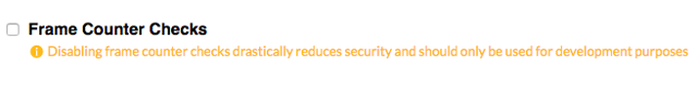
When using an ABP device, it’s important to disable the frame counter checks in the device settings on TTN. This is one of the things making it less secure.
Range Testing
By driving around with an end device node in my car, I’ve tried to determine my communication range with my gateway. I’ve been a bit disappointed, but there are many things that affect signal propagation. First, despite having an 10-foot antenna mast, my antenna is still not even close to being higher than my house. And I’m hardly an RF engineer when it comes to designing my custom end devices.
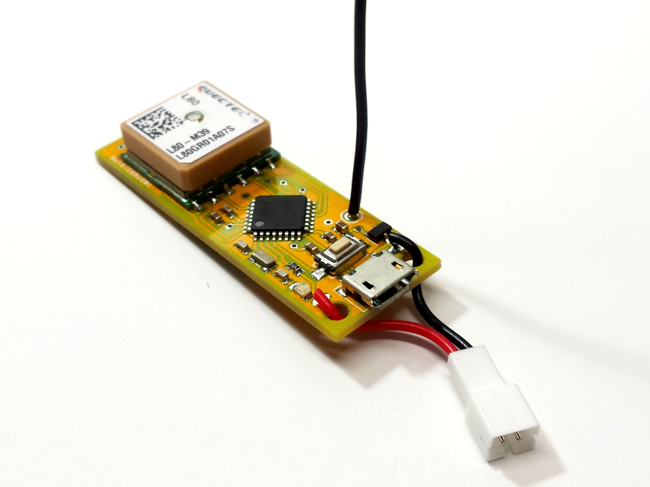
They have a simple wire antenna, but my prior experimentation led me to think that this was just as good as any other LoRa antenna I’ve tried. In one test, my son and I each strapped a LiPo battery powered end device to our bikes and went for a long ride, having each node send GPS data every minute to my gateway (I realize that this test used far more duty cycle than one should in a real application). A Cayenne dashboard mapped the received data from each device. The smooth path on the map is the actual path as measured by GPS in my son’s phone. Superimposed on this are two non-smooth paths defined by blue points at which the gateway “heard” the GPS data reported from the end-device. The gateway is in the southwest are of the map, and you can clearly see that it did not receive much data when we are on the northernmost part of our bike ride. The maximum distance for a received signal was about 1.2 miles.

I also experimented between using confirmed vs. unconfirmed messages. Confirmed message get an acknowledgement from the gateway, whereas unconfirmed are more like “fire and forget”. Counterintuitively, it seemed like confirmed messages were more reliable and had better range. Nonetheless, I will continue to do more range testing to try to improve the situation.
Node-RED Integration
An online service like Cayenne makes it super easy to integrate with TTN, but you can also integrate with your own software via MQTT. Data uplinked from your devices to your TTN application are published to MQTT topics that you can connect to in your own application. I love using Node-RED for all sorts of IoT fun. You can use MQTT nodes (here “nodes” refers to Node-RED components, not end devices) to receive the data published by TTN. To make it even easier, TTN has even written custom nodes for TTN integration. If you are a Node-RED junkie like me, I strongly recommend you look into this type of integration so that you can build just about anything based on data from LoRaWAN end devices.

I hope you found these posts about LoRaWAN useful. The learning curve is significant but it’s exciting when a technology is so new.
