3-Track Looper with Audio Mixing
This Audio Hacker project is similar to the Four-Sample 12-bit Sampler project but now we can loop the samples and mix them together. Now we call them “tracks” instead of samples. It demonstrates how audio samples can be combined so that they are mixed at the output.
Load the Audio Hacker example sketch File->Examples->Audio Hacker->Looper. With this sketch you can record 3 different tracks and play each of them back in a loop. You can adjust the loop delay by using a potentiometer associated with the track. The loop delay is the time delay before playing the sample again. A delay of 0 just plays the sample over and over again with no delay.
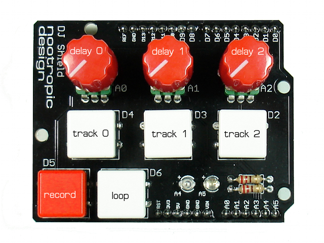
For this project, I used the DJ Shield because it provides all the buttons and pots.
You can build it on a breadboard if you want:
Record button = D5
Loop button = D6
Track 0 button = D4
Track 1 button = D3
Track 2 button = D2
Track 0 delay = A0
Track 1 delay = A1
Track 2 delay = A2
When the record button is tapped (pressed and released), it toggles the “passthrough” mode for the input. That is, when the sketch starts, the input is passed through to the output so you can hear it, but you can enable/disable the passthrough by tapping the record button.
To record a track, first enable the audio passthrough so you can hear the audio signal. Now press and hold the record button down, then hold down a track button to record the track. Release the track button when done recording, or if you exhaust the memory size for that track, the output will stop. To play the track (just once), press the track button. To cause the track to play in a loop, first press and hold the loop button, then press the track button. Now you can release the loop and track button, but the track will continue to play in a loop. Adjust the loop delay by adjusting the track’s potentiometer. To stop the looping of the track, tap the track button.
Now let’s record another track. Enable the input passthrough by tapping the record button. Now hold the record button and hold a new track button (like track 1) to record onto that track. Hold the loop button and tap the track button for your new track. Now tap the track button for the other track you recorded. They will both loop and will mix together. Go ahead and record a third track and loop them all together.
If the controls are confusing, just play with it for a while until you get the hang of it. You can enable debugging by uncommenting the line #define DEBUG and open the Arduino serial monitor with speed 115200. This will show you information about what is going on in the sketch.
Mixing Signals
Audio signals in this 8-bit project are represented as a series of 8-bit values in the range of [0,255]. Real audio signals are best described as waves that can have both positive and negative values, oscillating around a midpoint of zero. Audio signals mix together in an additive manner, where positive and negative values “cancel” each other out. Before we mix two signals together, first we normalize them so that the midpoint is 0 instead of 128. So 128 is subtracted from each value to give it a range of [-128,127] and we store the result in a signed integer. Now we add the values together to get the mixed signal.
It’s possible that two signals mixed together have exceed the maximum value of 127 or gone below the minimum value of -128. In this case we need to “clip” the value to the maximum or minimum. This will sound like distortion/noise when this happens. Read this for a better understanding of clipping.
After mixing signals together, we adjust the final value upward to the range of [0,255].
Performance Notes
In order to do all this mixing quickly, there are some compromises. The sample rate is 18 kHz and the samples are 8-bit audio.
The memory is divided up as follows: track 0 is on the first SRAM chip (128K) and can hold about 6 seconds. Tracks 1 and 2 split the second SRAM chip and are about 3 seconds each.
Four-Sample 12-bit Sampler
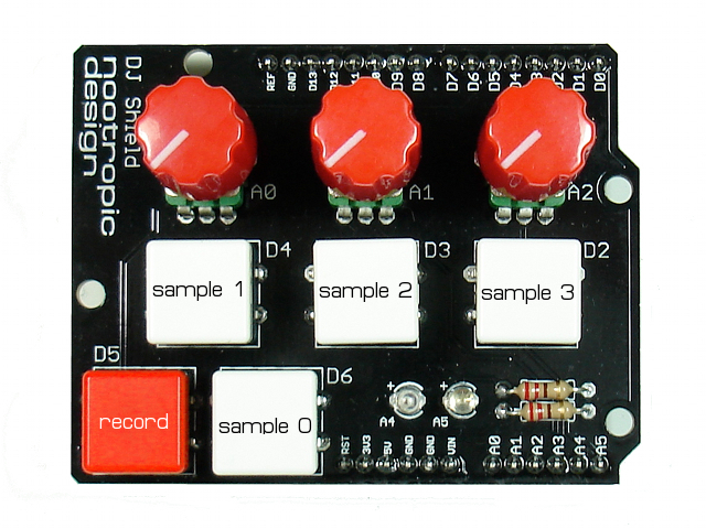
This Audio Hacker project is similar to the 12-bit Sampler, but divides the Audio Hacker SRAM into 4 banks so that you can record and play back 4 different samples. To make the hardware setup easy, we’re using the DJ Shield because it has 5 buttons. The 4 memory banks are assigned to the 4 samples like this:
You don’t have to use the DJ Shield if you put 5 buttons on a breadboard. The assignments should be:
Record button = D5
Sample 0 button = D6
Sample 1 button = D4
Sample 2 button = D3
Sample 3 button = D2
Load the Audio Hacker example sketch File->Examples->Audio Hacker->MultiSampler_12bit.
To record a sample, press and hold the record button down, then hold down a sample button to record it. Release the sample button when done recording, or if you exhaust the memory size for that sample, the output will stop. To play a sample, press and hold the sample button on which the sample was recorded. Now you can record and play back 4 different audio samples in the SRAM!
Realtime Adjustment of Sampling Rate and Bit Resolution
This Audio Hacker shield project lets you dynamically adjust the audio sampling rate and bit resolution so that you can listen to the effect they have on audio quality. With an Arduino and this simple shield, we can sample audio and manipulate the signal in many different ways.
Sampling rate is how often we measure the input voltage of an audio signal. The more often we measure it, the more faithfully we can reproduce the signal. According to the Nyquist Sampling Theorem, to reproduce a signal with frequency f, we must sample at a rate of 2f. So higher sample rates will allow us to reproduce higher frequencies and have less noise in the signal.
Bit resolution, or audio bit depth, refers to how accurately we measure the input voltage. A resolution of 8 bits means that each measurement has 8 bits of precision, giving us values in the range of 0-255. A resolution of 12 bits is more accurate and gives us values in the range 0-4095.
CD quality audio is 44.1 kHz sample rate with 16 bits of resolution. The Audio Hacker ADC (analog to digital converter) and DAC (digital to analog converter) are only capable of 12-bit resolution.
But how do these parameters affect the quality of audio? You can listen for yourself by connecting two potentiometers to the Arduino+Audio Hacker shield so we can adjust the sample rate and bit resolution while we are listening to an audio signal!
Load the Audio Hacker example sketch File->Examples->Audio Hacker->DynamicSampleRate onto your Arduino. Connect two potentiometers to pins A0 and A1. If you are unsure how to wire it, see analog input tutorial. A0 will control the sample rate and A1 will control the bit resolution. Set the pots both to their highest values and open the Arduino serial monitor (rate=115200) so you can see the output of the program. Play an audio signal into your Audio Hacker (e.g. from an MP3 player or from your music library on your computer). Now adjust the sampling rate downward until you hear the quality start to suffer. At what sample rate does it seem to start introducing noise? What does the noise sound like?
Now use the second potentiometer to adjust the resolution down from 12 bits to 11, then 10, then lower. Can you tell the difference between 12 bit resolution and 10 bit resolution? How about 8 bit resolution? Lowering the bandwidth of the signal is called “bitcrushing”. What happens when you crush it all the way down to 1-bit resolution? You might be surprised at how intelligible speech can be even with one bit of resolution!
This experiment isn’t a perfect test for sampling rate because there is a low pass filter on the input, so you may not hear much difference in audio quality as the sampling rate goes above 30 kHz. This project is good for hearing how things degrade at lower sampling rates and bit resolutions.
Now, which do you think is more important for audio quality: sample rate or bit resolution?
Full info about the Audio Hacker is here.
For lots more great Audio Hacker experiments, see the Audio Hacker project page.
The Audio Hacker is available as a kit or fully assembled in the nootropic design store.
Battery Backup for Audio Hacker Samples
When you record audio samples to the serial SRAM on the Audio Hacker, the data will be lost when power is disconnected. However, the Audio Hacker uses SRAM chips that allow a small voltage to maintain their contents. The Audio Hacker board has pads where you can connect a small battery.
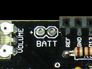
A 3V coin cell battery (like a CR2032) is sufficient to maintain the contents of the memory:
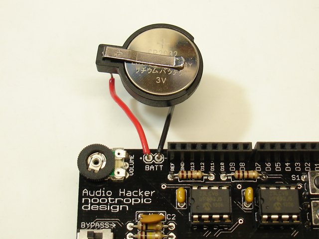
Now you can disconnect power without losing your awesome samples. There is one problem though: your sampling program on the Arduino was probably keeping track of which memory address your sample began/ended at, so now your program has “forgotten” where the sample boundaries are. One way to fix that is to write your sample address information to a header in SRAM. Another easy approach is to store the address info in the Arduino’s EEPROM. There is code in the Four Sample 12-bit Sampler project, as well as the 3-Track Looper project. These sketches store each sample’s end address in EEPROM whenever a sample is recorded. At sketch startup, these addresses are read from EEPROM. The code is simple, so just look for lines that use the EEPROM library.
Playing Audio Hacker Samples in Reverse
This simple example project is the same as the 12-bit Sampler, but the audio sample is played in reverse. In the Arduino menu, choose File->Examples->Audio Hacker->SamplerReverse. Record your audio sample with button S1 on the Audio Hacker (top button), and play it back in reverse using the S2 button. Just as with the 12-bit Sampler, you can connect a potentiometer to A0 to adjust the playback speed. If you are unsure how to wire the potentiometer, see analog input tutorial. To enable this feature, make a minor code change to set adjustablePlaybackSpeed = true;. Arduino will prompt you to save your changed sketch to another location.
