Difficulty Level = 7 [What’s this?]
Several people in the FPV RC world (that’s First Person View Remote Control for the uninitiated) have contacted me about the possibility of using a Video Experimenter shield as an OSD solution (on screen display). People who fly RC planes and helicopters are increasingly using on-board video cameras to provide a first-person view of the flight, and they like to overlay GPS data onto the video image. Flying radio controlled drones has become a huge hobby (just look how big the DIYDrones and RCGroups communities are!).
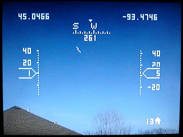
I don’t have any RC vehicles, so I’m really on the outside looking in, but I thought I’d experiment to see how useful a Video Experimenter might be in overlaying data onto a video feed. I wrote a simple Arduino program that reads GPS data from the Arduino’s serial RX pin and overlays a heads-up display onto the video input. I think it turned out pretty nice:
All relevant info is displayed: current latitude/longitude, compass heading, speed (left), altitude (right), and distance home (meters) in the lower right. There’s also a home arrow in the center of the screen pointing toward the hard-coded home location. Note that the ground elevation is also hard coded in the Arduino program so we can calculate altitude.
Circuit Setup
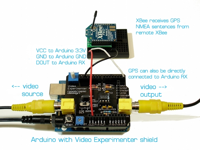
I think there are two ways that a FPV solution could use this approach. If the vehicle is transmitting video and also transmitting GPS telemetry via an XBee radio, then the GPS data can be overlayed onto the video at the ground station. I had to configure the XBee radios to use the same baud rate as my GPS (4800bps).
OR the Arduino and Video Experimenter shield could be onboard the vehicle itself. This way the GPS data is overlayed onto the video before the video is transmitted. In this case, the GPS module is connected directly to the Arduino RX pin, and there’s no XBee radios involved. An Arduino+Video Experimenter shield weigh 2 ounces or 57 grams (I knew you were going to ask that).
I need to be clear that this overlay software can’t run on your ArduPilot hardware. Processing video in an Arduino environment requires nearly all of the ATmega’s SRAM, so there’s no way that this is going to run on the same hardware as your autopilot code.
Again, I’m not in the FPV RC community and don’t have a plane, so I’m not entirely sure how feasible all this is. But a number of RC hobbyists have asked about the Video Experimenter and were enthusiastic about the possibilities. Comments are very welcome!
GPS Configuration
My EM-406 GPS module is configured to only output RMC and GGA sentences, and they are output once per second, so the display only updates at that frequency. It was important to limit the output to only the RMC and GGA sentences, because when using the Arduino video library (TVout), serial communication is accomplished by polling, and it can’t handle data too quickly. To limit the output to RMC and GGA sentences, I wrote these commands to the GPS RX line, with each line followed by a CR and LF character. The Arduino serial terminal works fine for this. Don’t write the comments, of course.
# enable RMC, output 1Hz:
$PSRF103,04,00,01,01*21

# enable GGA, output 1Hz:
$PSRF103,00,00,01,01*25

#disable GLL
$PSRF103,01,00,00,01*25

#disable GSA
$PSRF103,02,00,00,01*26

#disable GSV
$PSRF103,03,00,00,01*27

#desiable VTG
$PSRF103,05,00,00,01*21
If you have a MediaTek GPS module, I believe the correct command to disable all sentences except for RMC and GGA would be this:
$PGCMD,16,1,0,0,0,1*6A
I don’t know how fast of a data feed that the Arduino overlay code can handle, so some experimentation would be in order.
Download
Download the Arduino code OverlayGPS.zip. The awesome TinyGPS library is also required, so install it in your Arduino libraries folder. You also must use the TVout library for Video Experimenter that is required for Video Experimenter projects.


Am I right in thinking that the same can be done using just a gps module, some tiny avr (2313?) and lm1881n chip with some passive components? The thing is in the FPV world each gram makes sense, so all those bulk headers and other, non-necessary burden should be avoided if possible.
Yes, but you’d need to use at least an ATmega328, preferably an ATmega644. You need the memory. An ATtiny doesn’t have nearly enough memory for the frame buffer.
I have been able to run other video overlay demo sketches but I just cant get this GPS overlay to work. I think that my GPS is using NewSoftSerial and the video experimenter is using a regular serial input. Does this require a GPS input for the experimenter to display on my videos screen? I was at least expecting the lines on the side with no values for position or speed even without the GPS input. I would need some help modifying the code to make this work.
Brent, the sketch provided does not use NewSoftSerial or normal Serial library. It uses a polling Serial implementation in the TVout library. Your GPS unit doesn’t care either way. Did you configure your GPS module to only send the required NMEA sentences? If it sends too much, the Arduino won’t be able to keep up with the input.
Mike, I really dont know how to configure my GPS. I have the EM406 and have read your instructions over and over and I am totally lost.
@Brent,
OK, I’m not sure how else to explain the instructions. I gave the exact sentences to write to the GPS unit over the serial line. You can do this with a program using Serial.println or just use the Serial Monitor that comes with the Arduino IDE to write the sentences to the GPS unit.
Hello, I am looking to utilize a Standard and HD camera output that will have gps data overlay for land surveys. Can you assist in helping me develop such a product?
I’ve got this error when upload the Overlay GPS sketch, someone know what is the problem?
I’ve got this error when upload the Overlay GPS sketch, someone know what is the problem?
“OverlayGPS\bitmaps.cpp.o:(.progmem.data+0x0): multiple definition of `bitmaps’
bitmaps.cpp.o:(.progmem.data+0x0): first defined here”
Please let me know price about the Overlay GPS Data on Video
best regards