Difficulty Level = 10 [What’s this?]
I bought this awesome RGB LED matrix panel from Adafruit and really wanted to see if I could make it display video from an Android phone. It was somewhat difficult, but by using my Android phone, the OpenCV computer vision library for Android, a Sparkfun IOIO board, and an Arduino, I got it working.

All of the hardware and software setup details are below, but before I explain how it works, let’s see it in action:
How It Works
This is not a beginner project, so if you don’t have experience doing any Android development, you’ll need to be patient. Just getting your Eclipse development environment set up for Android development with the OpenCV and IOIO libraries took me a couple of hours, and I’ve been using Eclipse for about 10 years.
An Android app running on the phone captures video frames and processes them down to a lower resolution suitable for the 16×32 LED matrix. OpenCV is a powerful computer vision/image processing library, and there’s a version that runs on Android. I used the OpenCV library to convert the video frames to 16×32 pixel resolution to match the LED matrix. I also constrained the color space of the frames to 12 bit color. That is, each pixel has 4 bits each for red, green, and blue. That means that each pixel can have 16 different brightness levels of red/green/blue, yielding 4096 possible colors. In other words, all of the image processing is performed on the phone because it’s much more powerful than the Arduino.
The 16×32 12-bit image uses 1024 bytes of memory on the phone (2 bytes per pixel). The Android then uses the IOIO library to write this data out one of the IOIO board’s serial ports. Each frame starts with a two-byte frame marker 0xF0 0x00, then the bytes for the pixel values are written. The performance bottleneck is between the phone and the IOIO board. I can only write about 4 frames per second, even though the serial interface between the IOIO and Arduino is 115200 baud. Since each pixel really only needs 1.5 bytes instead of 2, I could pack the pixel data tighter to get perhaps one more frame per second, but didn’t think it was worth the trouble.
The green wire in the picture below is a serial connection from the IOIO and Arduino. The Arduino code simply reads the pixel values, using the frame marker to know when a new frame begins. The pixel values are written to the LED matrix panel using the Adafruit library for controlling the panel. Driving this matrix is no small feat for the Arduino, since the matrix panel does not do any PWM on its own; the Arduino needs to generate the PWM. This matrix driver software could have been written for the IOIO to control the matrix directly without an Arduino, but Adafruit had really tuned this library for high-performance and very precise timing, so I thought I’d better stay with the Arduino code for now. The result is video at about 4 frames per second. Not very fast, but the color rendition is pretty good.
Hardware Setup

The RGB matrix panel is wired to the Arduino just as Adafruit’s instructions describe. They have an excellent page that describes how the panel works and how to use it.
The RGB matrix and the Arduino are powered by a 5V regulated power supply that can provide 2A (also from Adafruit). The IOIO board is powered independently by a 9V supply that can provide 1A. It’s important to provide plenty of current to the IOIO board so that the phone can charge, however you can adjust a potentiometer on the IOIO to reduce the charging current. As with any project with multiple power supplies, all the grounds must be connected. A single green wire provides the serial data feed from the IOIO to the Arduino RX pin.
I used a diffuser in front of the display to make it look much better. Without a diffuser, the LEDs are simply blinding and it’s not easy to see any image. My diffuser is a piece of acrylic with paper vellum on it. The diffuser is held about 5mm in front of the LED panel (with a little roll of duct tape as a spacer).

The phone (a Samsung Nexus S) is connected to the IOIO via USB. I mounted above the panel by holding it very gently with a Panavise.

Software Setup
Android + IOIO + OpenCV Software
The hardest part of the software setup is preparing your development environment for Android, IOIO, and OpenCV development. The details of how to do this are beyond the scope of this article, but all of the steps are documented in various places.
- Set up your Android development environment: this is documented on the Android SDK website. After you have performed this step, you will be able to write simple Android programs and run them on your phone.
- Install the IOIO library: see this great Sparkfun tutorial which describes how to run Android apps that communicate with a connected IOIO board. After you have performed this step, you will be able to upload the HelloIOIO app to your phone and have it communicate with your IOIO board. Don’t move on to the next step until you are sure you have the IOIO working with your phone.
- Install the OpenCV library for Android by following these instructions. After successfully doing this, you should be able to run the OpenCV Android examples on your Android phone. Don’t proceed until you have this working successfully.
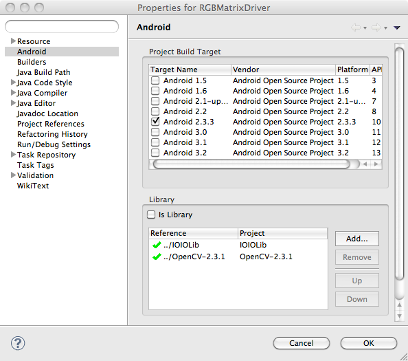
- Now that you have all the supporting libraries in place, download the RGBMatrixDriver Android application project and install it in your Eclipse workspace and open it. With luck, it will compile cleanly. If not, make sure that the project is correctly pointing to the IOIO and OpenCV libraries as in the image below.
- You may need to customize the code a bit. I used IOIO pin 7 to send serial data to the Arduino, so you may need to change the pins specified in the call to
openUartinRGBMatrixActivity.java. You may also need to change some screen dimensions specified inRGBMatrixView.javato work with your phone — just follow the comments.
Once you have the application running on your phone, this is what it looks like in action. The video image is displayed with the same resolution and colors as the RGB matrix.
Arduino Software
Now that the hard part is done, it’s easy to get the Arduino software installed.
- First, you’ll need Adafruit’s library for driving the panel. This project uses a slightly older version which you can find here. Install it in your Arduino sketchbook libraries folder just like any other library.
- Then download and install the
RGBMatrixSerialsketch and install it in your Arduino sketchbook. Compile it and upload it onto your Arduino. The sketch is so simple, I’ll show the whole thing here:#include "RGBmatrixPanel.h" #define A A0 #define B A1 #define C A2 #define CLK 8 #define LAT A3 #define OE 9 #define WIDTH 32 int count = 0; byte currentByte = 0; byte lastByte = 0; uint16_t color; RGBmatrixPanel matrix(A, B, C, CLK, LAT, OE, true); void setup() { Serial.begin(115200); matrix.begin(); } void loop() { int index; while (Serial.available()) { lastByte = currentByte; currentByte = Serial.read(); // Look for the frame marker 0xF000 if ((lastByte == 0xF0) && (currentByte == 0x00)) { count = 0; matrix.swapBuffers(false); } else { if ((count % 2) == 1) { color = (lastByte << 8) | currentByte; index = (count-1)/2; matrix.drawPixel(index % WIDTH, index / WIDTH, color); } count++; } } }
Future Ideas
- increase the framerate a bit by packing 2 pixels in 3 bytes of transmitted data (only really need 1.5 bytes per pixel), but need different frame marker detection.
- use the 32x32 matrix panel from Adafruit
- try BlueTooth connection between phone and IOIO board (need to upgrade IOIO firmware)
- Get an Arduino Mega ADK and use it to interface with the Android phone instead of the IOIO. The framerate should be higher.

Great project!
A few thoughts that crossed my mind:
1. You probably don’t need the Arduino. With some effort the IOIO firmware can do the same.
2. You mentioned that the Android IOIO bandwidth is the bottleneck. I find it hard to believe. You may want to try the newly released OpenAccessory mode in IOIO which will give you better throughout.
3. Bluetooth will definitely give you worse throughput although as I said, I don’t think that’s the problem.
4. There are faster protocols than UART you can use. SPI can give you much better throuput.
Ytai, thanks for the comments and suggestions, and most of all, thanks for inventing the IOIO. I think it’s great. As far as communication speed, I carefully measured how fast I could write bytes from the phone through the IOIO UART and to the Arduinio, and was maxed out at about 4K/s. I’m sure the Open Accessory firmware would help, as well as an SPI approach. I need to try those options. And I’m sure with a lot of effort, I could write firmware on the IOIO to drive the RGB display, but Adafruit had already done the heavy lifting to get it to work well, and it required extremely precise timing and inline assembly to drive it efficiently since the display doesn’t do PWM on its own.
Thanks again for writing…I plan on doing more IOIO projects.
Unreal project. I guess I need to get into Open CV. Agree with Ytai that you could have done the work sans Arduino, but in all, this is one of the coolest builds I’ve come across. Cheers!
Hi Michael,
I’m in College, in Electronic course, and I liked your project very much.
I’m trying to do a project similar to yours, but using a PC instead of Android, and generating random videos using a Windos Media Playes Plugin, but I am facing problems regarding the interface between the PC and the Arduino. In your case the card IOIO solved the problem. Could you tell me if there is a card similar to IOIO for PC, or another possibility to make this interface?I’ve just bought this same board of Adafruit as well
You can answer me by e-mail if you want.
Thank you very much for the help,
Johnson
Johnson, you don’t need any special hardware to communicate with the Arduino from a PC. Just the USB cable. The IOIO board was required for Android because Android needs a USB host.
Thank You Michael,
I thought I would need something like that to get the video information and convert to the Board.
Thanks again, very nice project your!
BR
Greetings Michael!!
I am an Engineering student from India & I am trying to replicate your project. So far I’m absolutely enjoying myself. I have managed to procure the Arduino and IOIO boards; however I have been unable to acquire the RGB matrix. I am now trying to continue the project using a soi-disant matrix which is monotonous. Please advise me, on what changes I should make to the programs, if I have to use a matrix of regular LED’s. Seasons greetings to you. I am awaiting your response. Thank you sir.
-Prashi
Well, the project would need to be completely changed to work with a different matrix technology. I don’t have any idea how to drive your matrix with an Arduino, so I have no idea how it would need to change. You will need to figure out how to drive your matrix with an Arduino and work forward from there. Or obtain the Adafruit matrix.
Thank you sir. I will try to figure it out.
If I manage to drive my matrix with the Arduino, I will be required, to pass a single intensity value to each LED instead of the three values that are being passed for red, green and blue in the Adafruit matrix. If I make progress in driving my matrix, I will get back to you for help.
Regards
-Prashi
Greetings ! We have obtained the Adafruit matrix but now we are having trouble running the app. successfully on it. We are able to get only green and blue on the matrix while running the app.; no red. Where could we have made an error? Please help us out….
……We have used a 12V 1A supply for the IOIO board and a 5V 1A supply for the Matrix. The Arduino is being powered through the USB. Is the power supply the problem?
All the test sketches for the Adafruit board are running perfectly(i.e. with red in them too)
Are you saying that my demo code is not displaying any red, but Adafruit demo sketches are displaying red? I don’t know how that would happen — my demo sketch uses the Adafruit library.
Make sure all your grounds are connected. Arduino ground connected to the grounds of the other power supplies.
NO sir we are not saying anything about your code….We want your advice to troubleshoot this project..we have double checked our grounds..is there any other mistake we could have made?
It looks like Adafruit changed the format of the color in their library. So the values sent by my Android sketch no longer work. Try downloading this older version of the Adafruit library: http://nootropicdesign.com/projectlab/downloads/RGBmatrixPanel.zip
You were right, the older version of the library worked perfectly with your code. To see the matrix light up in full glory was very satisfying.
We have gained a lot through this project. As you have said on your website, we really do feel empowered to find answers ourselves now, although of-course, we did require your support. Thank you sir, for your prompt responses.
That’s great to hear! Never forget that you can solve any technical problem if you keep trying. Never give up!
Dear Michael is it normal that the android application crash (i Mean that it give on the phone to terminate the application) if the ioio board is not connected?
Americo, that would not surprise me. It’s been a long time since I did this project, so I don’t quite remember if that’s normal.
Hy Michael i’ve ordered a ioio otg the ultimate version, did you think i’ve to change something or it should be work with it normally ? If not what changes i need to do on the code itself?
I really don’t know if you’ll need to make changes. I don’t have an IOIO OTG device. You’ll just have to try it out.
Sorry Michael if i border you again but i need a hand on this project that is so great can you give me an email to contact you ? my problem is on the android part one the rest works very well i do not kno how to solve it plese help me my app crash and never start up i do not know how to solve it
We have a question concerning the post, where am i able
to make contact with the author?
Elizabeth Lee, my contact info is on the About page on my site: https://nootropicdesign.com/about.html