Hackvision Featured in Make Vol. 25
This isn’t really a project, but I wanted to brag about Hackvision being featured in the Volume 25 print edition of Make Magazine. It’s on p. 77. Thanks, John Baichtal for the great writeup!

Wireless Temperature Sensor using RF Transmitter/Receiver
Difficulty Level = 5 [What’s this?]
UPDATE: Also see this project for an easy way to display a temperature reading: Digit Shield Temperature Display.
A while back, I did a wireless temperature sensor project using XBee radios. XBee radios are really powerful devices with good reliability and the ability to read and transmit sensor readings without a microcontroller. BUT, they are difficult for people to configure, the documentation is hard to understand, and it’s really difficult to parse the API data packets at the receiving station. So I decided to try the same project using inexpensive RF devices. I used a 434MHz transmitter ($4) and receiver ($5) from Sparkfun, and had great success with these cheap devices. I also used a simple LM34 Fahrenheit temperature sensor, two Arduinos (one was a homemade breadboard version), and a two-digit LED display to show the temperature at the receiver end.
The Receiver
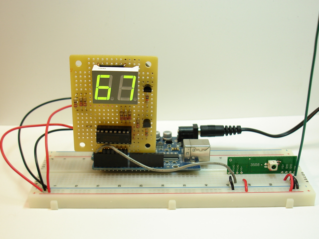
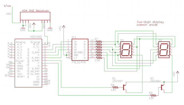
I used a single 74LS247 BCD to 7-segment driver chip for the display. The segment pins of the two digits are connected together, so I need to multiplex between the digits to show only one at a time. The multiplexing is so fast, there’s no flicker. The segments have common anodes and I used two PNP transistors to provide current to the anodes. Don’t ever drive the anodes directly from an Arduino output pin because it’s too much current!
The RF receiver’s data pin is connected to the RX pin on the Arduino so we can just use the Serial library to read data at a slow 1200 bps. That is fast enough for temperature sensor readings. A 17cm antenna (the green wire) is attached to the ANT pin on the RF receiver.
Here is the code running on the receiver Arduino. These RF devices can pick up a lot of noise, so drawing on the work of others, I used a simple protocol which includes a packet header with a network identifier and target address, the data, and a checksum to catch errors. This provides robustness for the communication link.
read more…
A Halloween Costume with Source Code
Difficulty Level = 5 [What’s this?]
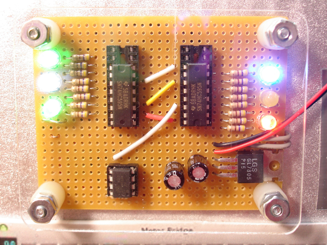
Like many parents, we make hand-made costumes for our kids instead of buying cheaply-made (and expensive) costumes based on licensed characters. This year, my youngest son wanted to be a robot. My wife did a great job making the costume, but I just had to add some cool electronics to take it to the next level.
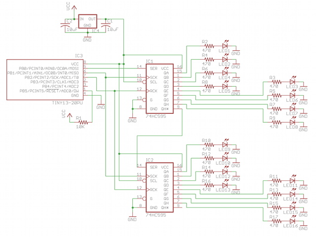
The electronics are nothing fancy — a simple Atmel ATtiny13 microcontroller that interfaces with two 74HC595 shift registers to light up LEDs randomly. The technical details are below, but in the process of building this, I was really struck by how electronics and computing are being embedded into everything. This week I was making a TODO list and one of the items was “finish source code for robot costume”.
OMG, now the costumes we make have source code.
This is a great example of how technology is becoming increasingly ubiquitous. Ten years ago, this would have been far beyond my reach. But in 2010 I can build this easily. The microcontroller cost $1.04, the shift register chips are $0.25 each, the resistors are a penny each, and the LEDs probably average $0.20 each. Definitely less than $5 for everything.
Technical Details
Here’s the schematic:
And finally, the simple source code that runs on the chip. I use CrossPack for AVR development. I use avrdude and a Bus Pirate to upload the code onto the ATtiny13 chip.
/*
 * ATtiny13 driving two 74HC595 shift registers
 *
 * Randomly turns on/off output pins of the shift
 * register ICs.
 * A random number of outputs are set high, then
 * a random time delay occurs.  Then the cycle
 *  repeats.
 *
 */

#include <stdlib.h>
#include <avr/io.h>
#include <util/delay.h>

#define DATA PB0
#define CLOCK PB1
#define LATCH PB2

int main(void) {
  int d;
  char n;
  char i;

  // set DATA, LATCH and CLOCK pins to OUTPUT
  DDRB |= (1 << DATA);
  DDRB |= (1 << LATCH);
  DDRB |= (1 << CLOCK);
  PORTB = 0;

  for(;;) {
    // choose number of LEDs to light up.
    // n will be between 4 and 16
    n = 4 + (random() % 13);

    for(i=0;i<16;i++) {
      // for each LED, probability of it being lit
      // is n/16
      if ((random() % 16) <= n) {
	PORTB |= (1 << DATA);  // set DATA pin high
      } else {
	PORTB &= ~(1 << DATA); // set DATA pin low
      }

      // toggle shift register clock pin
      PORTB |= (1 << CLOCK);
      _delay_ms(2);
      PORTB &= ~(1 << CLOCK);
    }

    // once we've shifted out all 16 values, toggle
    // the latch pin.
    PORTB |= (1 << LATCH);
    _delay_ms(2);
    PORTB &= ~(1 << LATCH);

    // delay random amount of time between
    // 100ms and 500ms
    d = 100 + (random() % 400);
    for(i=0;i<d;i++) {
      // _delay_ms function must be called with a
      // constant value, not a variable!
      _delay_ms(1);
    }

  }
  return 0; // not reached
}
Hackvision Now Available

Hackvision is now available in the nootropic design store. Available as a kit or fully assembled and tested.
