LoRaWAN Networking Part 1: The Gateway
I have been playing with LoRa modules a lot recently (see projects LoRa Weather Station and LoRa Mesh Networking) and even designed my own LoRa development boards. LoRa is an easy way to achieve low-power, long range radio communication with small payloads. To get even more capability out of this radio technology, you can set up a LoRaWAN network that is connected to the Internet and allows mobile nodes to hop between gateways, just like your mobile phone connects to different cell towers as you move around. So this summer I was determined to set up a low-cost LoRaWAN gateway and get it up and running on The Things Network. It was easier than I thought.
Gateway Hardware
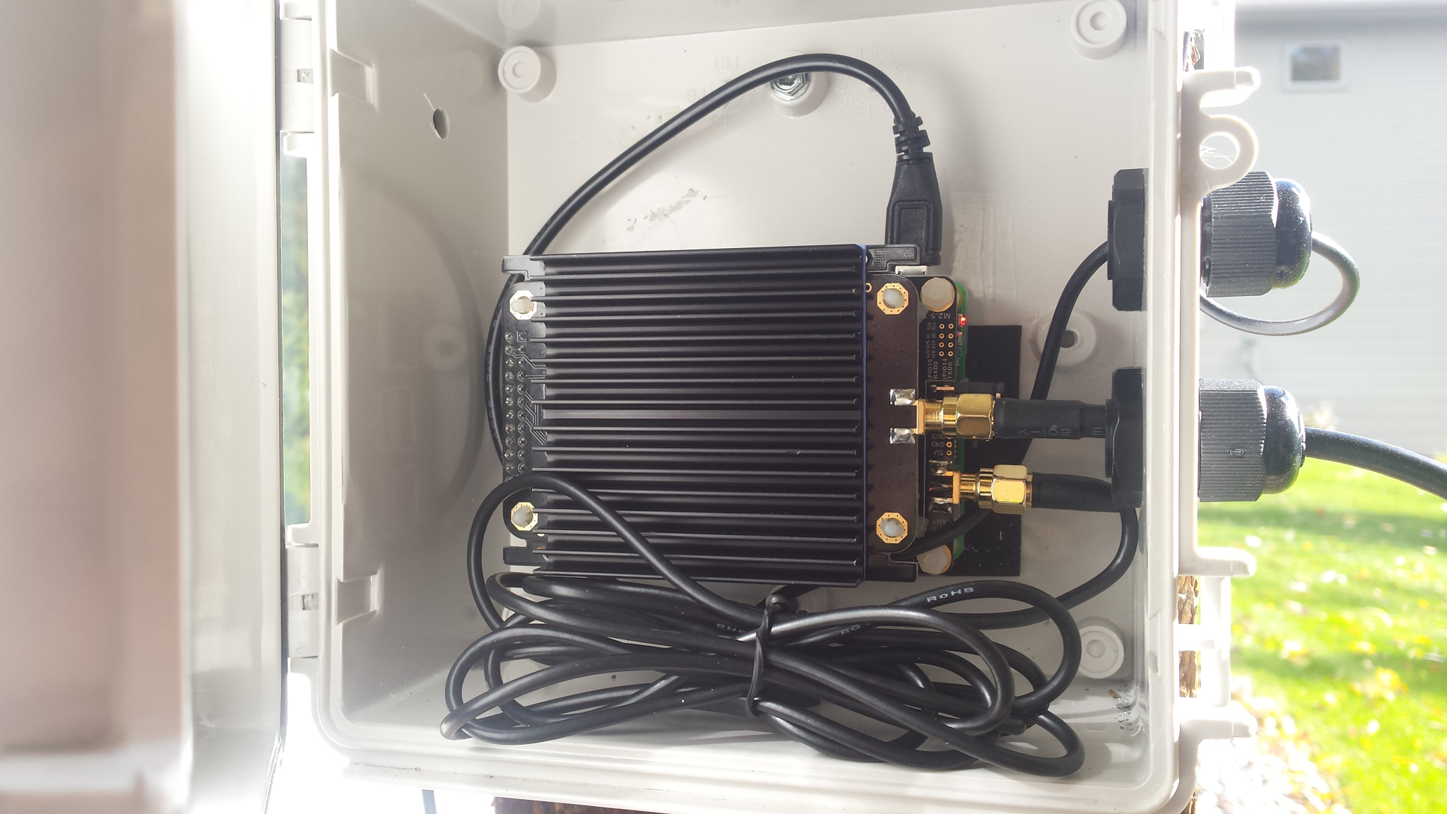
A gateway is an Internet-connected LoRa device that listens to multiple LoRa channels and forwards packets between the network backhaul (e.g. The Things Network) and the end device nodes it hears. Think of it like a cell tower for lower-power, mobile end device nodes. There are several gateways to choose from and I decided to try the RAK831 gateway from RAK Wireless, a Chinese company. The RAK831 is a LoRaWAN concentrator board that connects to a Raspberry Pi. I bought their LoRaWAN starter kit because it seemed to have everything you need.
In fact, it had more than I really needed. Here are the components that were essential to me:
- RAK831 LoRaWAN concentrator board
- Raspberry Pi 3 with SD card preloaded with all the drivers and setup for The Things Network
- Converter board to attach the RAK831 to the Raspberry Pi. This board also has a GPS receiver on it.
- GPS antenna
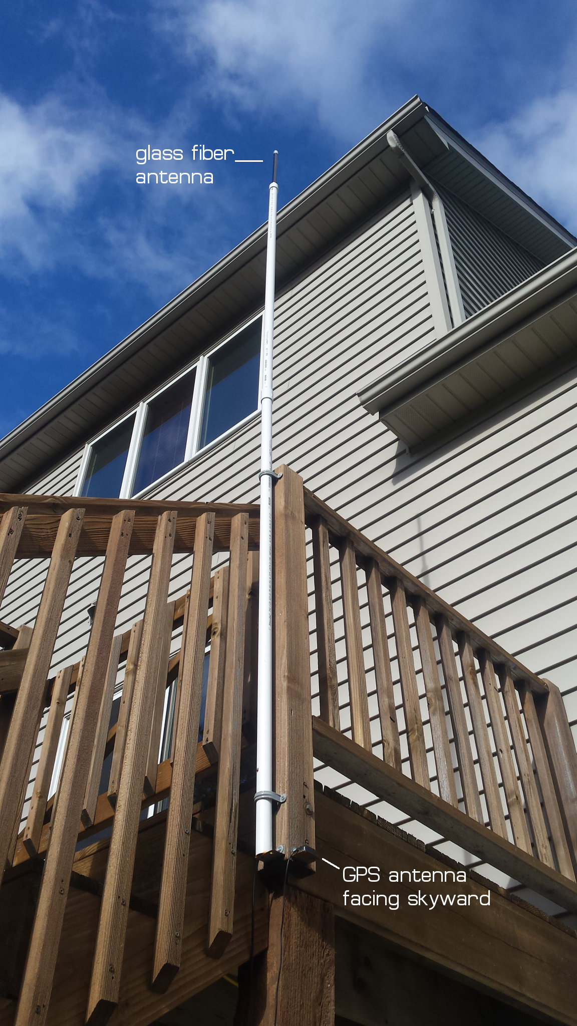
- Glass fiber antenna with 6dBm gain, so I could set up a tall antenna mast
- a 5 meter RG-58 tie line for the antenna
- heat sink for the concentrator board. I’m not sure it’s necessary.
The kit also came with a WisNode board which is like an Arduino + LoRa end device. It also came with a board called a LoRa Tracker, which I found useless because it requires some strange programming environment to use. Besides I had already designed my own end devices with GPS.
Configuration
I got a lot of information from this article on hackster.io about how to configure the Raspberry Pi to connect to The Things Network. Many of the steps are not necessary because the required software was preloaded. I did not have to enable SPI on the Raspberry Pi, or download the iC880a-based gateway software from GitHub. This had already been done.
I did set my WiFi credentials in /etc/wpa_supplicant/wpa_supplicant.conf as instructed.
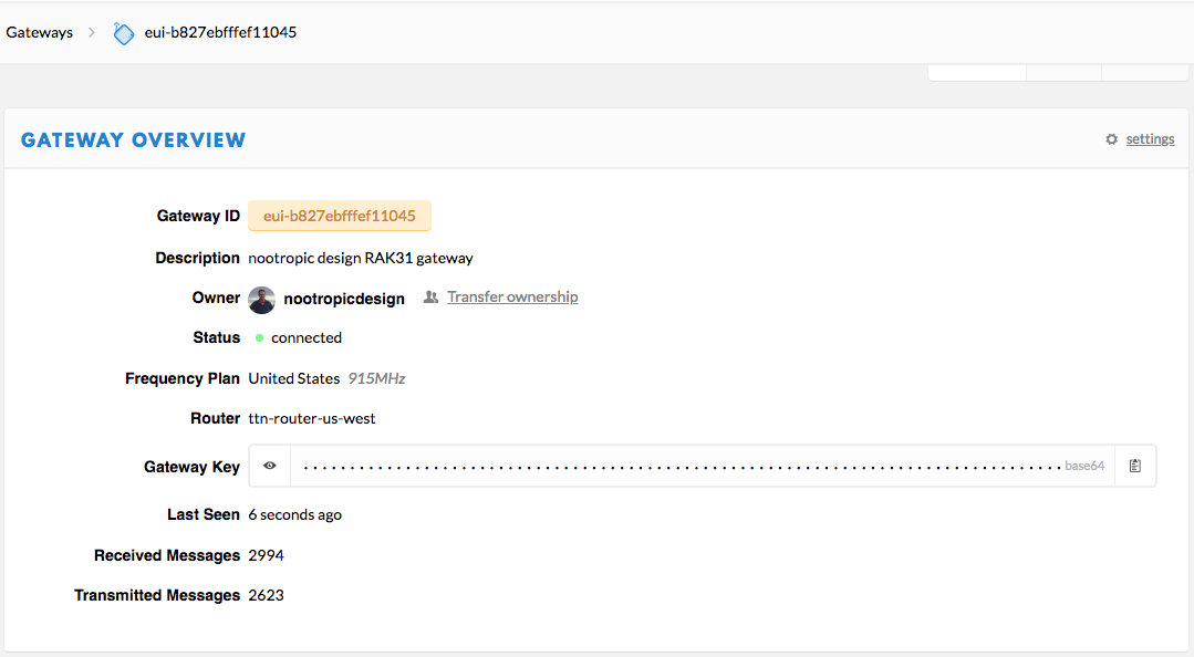
Then the main task is to set up the configuration file for the gateway. First, you need to determine the gateway ID. It is unique to the hardware because it is based on the MAC address of the network interface. Here’s a handy script to get it:
GATEWAY_ID=$(ip link show eth0 | awk '/ether/ {print $2}' | awk -F\: '{print $1$2$3"FFFE"$4$5$6}'); echo ${GATEWAY_ID^^}
Configuring the gateway is a little confusing. First, there’s a global configuration file that is not specific to your gateway but is specific to the region you are operating in (EU, US, Australia, etc.). I’m in the US, so I used the US global configuration file from the Things Network’s gateway-conf project on GitHub.
The gateway_conf section near the end is the important part. This has the correct router information for your region. This file goes in /opt/ttn-gateway/bin. IMPORTANT: in order for my gateway to work, I had to enable GPS in the global_config.json file by adding this to the gateway_conf section:
{
  "gateway_conf": {
  	...

    "gps": true,
    "gps_tty_path": "/dev/ttyAMA0",
    "fake_gps": false,

  	...
  }
}
Information specific to your gateway goes in a file /opt/ttn-gateway/bin/local_config.json. Here you use the key information from the global_config.json plus your gateway_ID, location information about where your gateway is, and contact info. Here’s mine:
{
  "gateway_conf": {
    "gateway_ID": "B827EBFFFEF11045",
    "servers": [
      {
        "server_address": "router.us.thethings.network",
        "serv_port_up": 1700,
        "serv_port_down": 1700,
        "serv_enabled": true
      }
    ],
    "ref_latitude": 45.0466,
    "ref_longitude": -93.4747,
    "ref_altitude": 277,
    "contact_email": "michael@nootropicdesign.com",
    "description": "nootropic design RAK831 LoRa gateway"
  }
}
When the gateway starts, the local_config.json info is merged with the global_config.json information.
The tricky thing is that your gateway configuration can be controlled by a remote file in GitHub. The gateway-remote-config GitHub repo is a collection of many local config files for TTN Gateways. When your gateway starts up, it actually pulls the latest content from GitHub. If it finds a file for your gateway, it removes the local_config.json file and creates a symbolic link from bin/local_config.json to the file in the cloned repo on your Raspberry Pi!
If you want to do this, fork the gateway-remote-config repo on GitHub, commit your own local config file to your forked repo named for your GatewayID (e.g. B827EBFFFEF11045.json), and then submit a pull request to the master repo. In a few days, your local configuration file will be merged and when your gateway starts, it will use it.
My final configuration is the /opt/ttn-gateway/bin/local_config.json which is a link to the
my config file in GitHub. The gateway_conf section in global_config.json simply contains this:
{
  "gateway_conf": {
    "gps": true,
    "gps_tty_path": "/dev/ttyAMA0",
    "fake_gps": false
  }
}
The Things Network
You’ll need to register your gateway on The Things Network using their registration instructions. This is easy.
Enclosure and Antenna
I mounted my gateway in a waterproof enclosure with wires going in for the 5V power, LoRa antenna, and GPS antenna. It did not get too hot in the summer, and I will soon see how well it fares in a Minnesota winter. I am hoping that the heat generated by the enclosed Raspberry Pi will keep the hardware from freezing, but I have no idea! UPDATE: the Raspberry Pi had no problems even when it was -28F (-33C) !!!
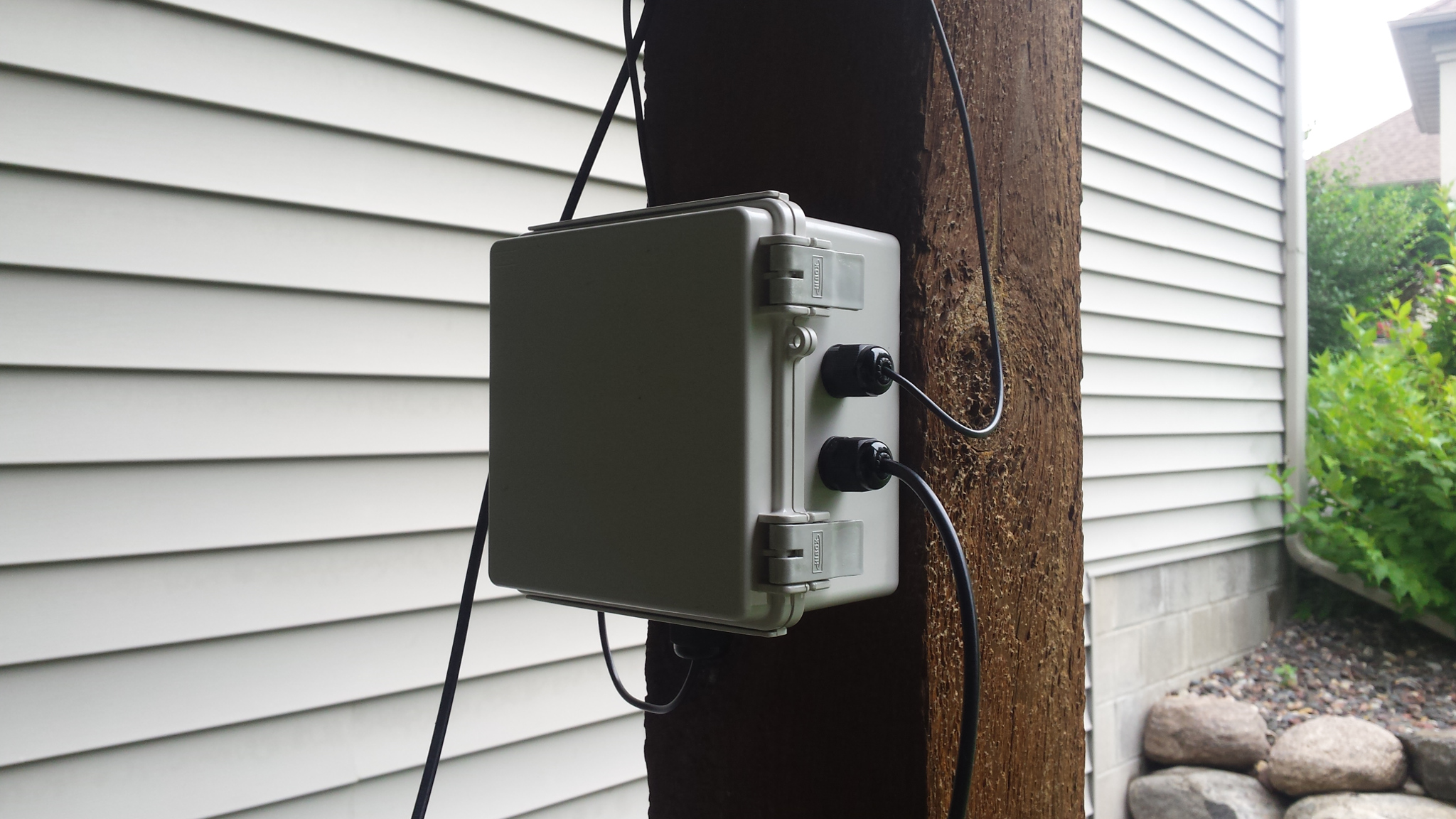
The antenna mast is PVC pipe and I used a 5 meter RG-58 cable to connect the concentrator board to the glass fiber antenna. There is power loss in 5 meters of cable, but the antenna still provides a net gain after accounting for this. I think it looks great and I hope my neighbors don’t think it is an eyesore.
In Part 2 of this article I’ll get into the details of using LoRaWAN nodes with the gateway. Stay tuned.
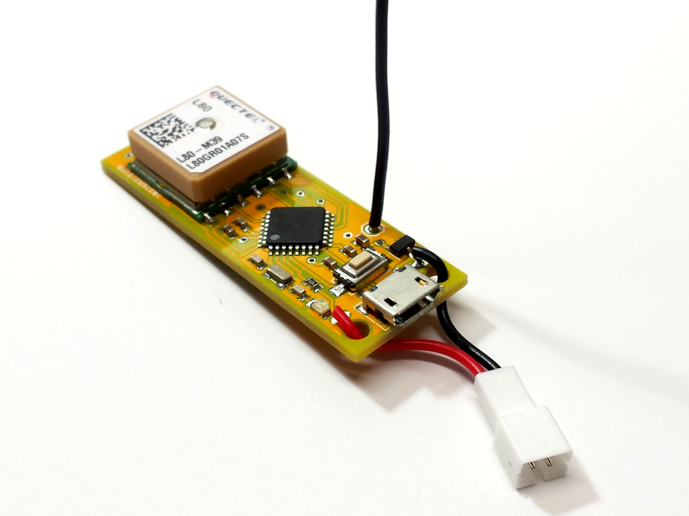
SAMD21 LoRa Development Board with GPS
Project source code at GitHub: samd21-lora-gps
I’ve been doing some LoRa projects lately in order to learn as much as I can about this exciting new radio technology (see this LoRa mesh networking project and this LoRa weather station). ATmega328-based Moteino modules work great for a lot of projects, but I wanted a LoRa node with more processing power, more memory, and an onboard GPS receiver. The ATmega328 is just too constrained with memory — I’ve outgrown it. I really wanted a LoRa board with an ARM Cortex microcontroller like the SAMD21. This is the microcontroller used on the Arduino Zero. So, my ideal board is a SAMD21 with LoRa radio module and GPS receiver, all programmable with the Arduino IDE.
But, where is such a board? I could not find one so I decided to design and make one myself.
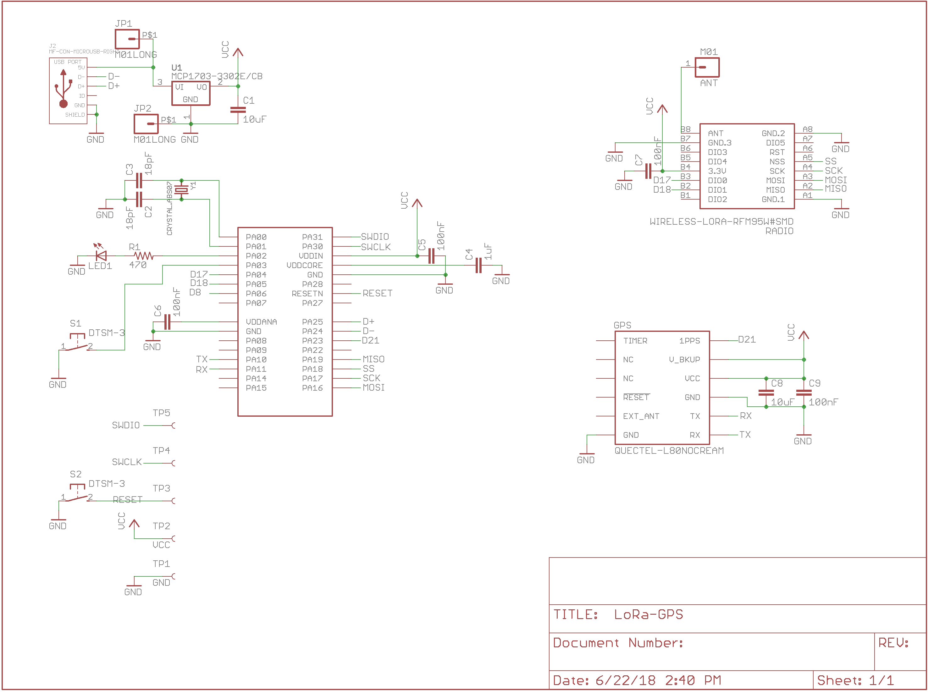
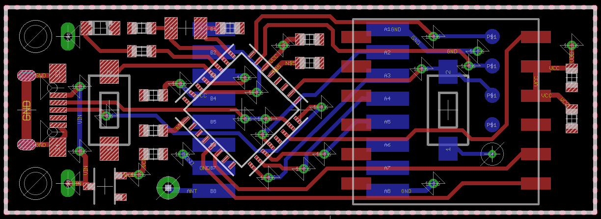
Hardware Design
Microchip/Atmel makes a SAMD21 chip and there are several variants. Most designs use the ‘G’ variant, but I wanted to use the simpler ‘E’ variant because it comes in a TQFP-32 package that I can very easily solder in my reflow oven without any trouble, or even by hand if I have to.
The GPS module is a cheap Quectel L80 with a MTK3339 chipset. It is easy to use but the backup power circuit requires a charging circuit, so I don’t have battery backup for quick startup. I mainly chose this module because it has big soldering pads with 2.54mm spacing for easier prototyping.
The LoRa radio module is a HopeRF module soldered to the bottom of the board.
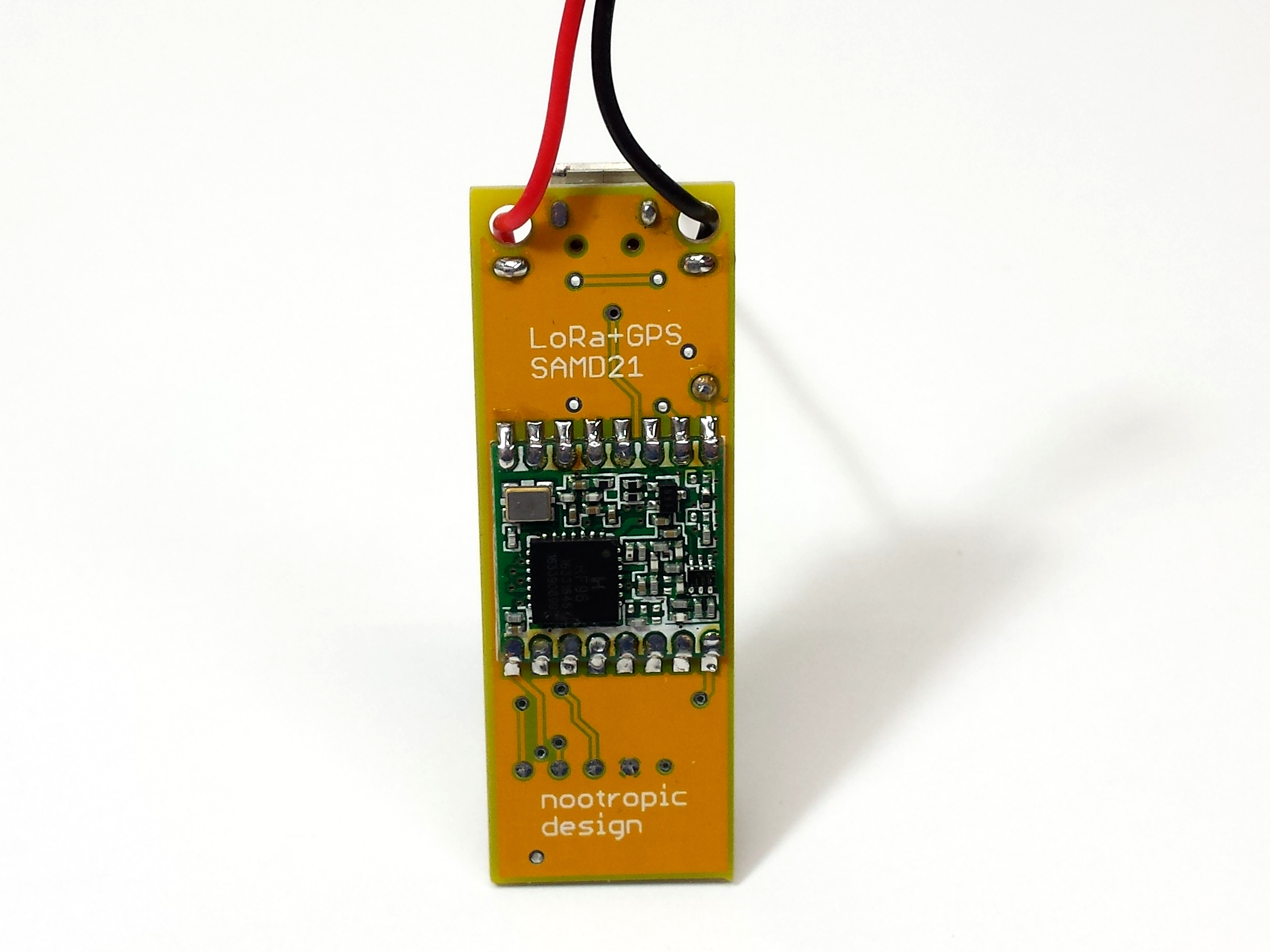
Here is the schematic and image of the board design. The Eagle files are in the hardware directory of the samd21-lora-gps GitHub repo.
Burning a Bootloader
To make this board work with Arduino, I had to burn the Arduino bootloader onto the chip using an Atmel-ICE programmer. My board has 5 test points on the bottom for this purpose. The Atmel-ICE needs connections for VTG (3.3V), SWDIO, SWCLK, RESET, and GND. The board has to be powered over USB during the programming procedure. In the Arduino IDE, I selected Tools->Board = Arduino/Genuino Zero (Programming Port), Tools->Programmer = Atmel-ICE, and then just clicked Tools->Burn Bootloader. In a few seconds, my board had a bootloader and is now programmable as an Arduino Zero!
Programming the Board
I was careful in my design to allow this board to be used as an ordinary Arduino Zero even though it uses a different variant of the SAMD21 chip. The downside of this is that the default SPI pins defined for the Arduino Zero board use pins that are not present in the ‘E’ variant of the SAMD21. Luckily the design of the Arduino system is flexible enough that we can define a different SPI interface on different pins. There is a great article by Adafruit on this topic but it may be pretty hard to understand. The bottom line is that by using these lines in your Arduino sketch:
SPIClass SPI1(&sercom1, 12, 13, 11, SPI_PAD_0_SCK_1, SERCOM_RX_PAD_3);
pinPeripheral(11, PIO_SERCOM);
pinPeripheral(12, PIO_SERCOM);
pinPeripheral(13, PIO_SERCOM);
You can now use interface SPI1 to communicate with the LoRa module. I wrote a simple test sketch that reads the GPS module and broadcasts the GPS coordinates on the radio every 15 seconds. See the samd21-lora-gps GitHub repo.
This test code uses the RadioHead library to control the LoRa radio. The RadioHead library is flexible so I was able to use the SPI1 interface by defining a couple of new files, RHHardwareSPI1.[cpp,h].
LoRa Mesh Networking with Simple Arduino-Based Modules
Project source code at GitHub: lora-mesh
In this project, I will show you how I built a mesh network of 4 Arduino-Based LoRa modules and devised a way to visualize the network’s behavior in realtime. Using a realtime visualization we can see how the network forms and how it heals itself when network nodes become unreachable.
By now you’ve probably heard of LoRa (“long range”) radio technology. It is intended for reliable communication of small amounts of data over long distances (several kilometers). It’s also geared toward low power applications. LoRa modules are relatively cheap (about $8 for a bare module), but the easiest way to use LoRa is to buy development boards that also have a microcontroller on them, like the Moteino.
LoRa radios can be used for point-to-point communication, and can also be used in a LoRaWAN network which involves communication with a centralized base station. This article, however, discusses a different approach: mesh networking of LoRa nodes. Mesh networking is a network topology where nodes communicate with one another either directly (if they are in range) or indirectly via intermediate nodes. For example, if node 1 wants to send a message to node 2, but is too far away from node 2, the message will automatically be routed via an intermediate node that is in range, say Node 3.
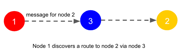
In fact, the path may involve several intermediate nodes. The discovery of the route from 1 to 2 is handled by a mesh networking layer — your application code doesn’t need to know anything about the routing. With mesh networking, LoRa nodes can be spread out across a further distance but can still communicate with one another as long as there is some connectivity between nodes in the mesh. Every node can talk to every other node, even though the network is only partially connected. Sound familiar? This is pretty much the architecture of the Internet. The robustness lies with the ability to route around damage and find new routes.
Mesh Networking in Arduino Code
How do we accomplish mesh networking with simple LoRa radios? If you have used LoRa radios before, you probably used the RadioHead library. We will use it in this project, too, because it includes an implementation of mesh networking. For details on how the mesh works, see the RadioHead documentation about it. I wrote an Arduino sketch to run on each of 4 Moteino boards so that each node will form a part of the network. Each node has an identity (e.g. “2”) which is stored in the device EEPROM.
First a note about the difficulty of testing mesh networks. It’s hard to place the nodes in such a way that only some nodes can communicate directly. To do so, I’d have to put my nodes far apart all over my neighborhood. Lucky, the RadioHead library has several test networks defined so that you can force some nodes to not be able to communicate. When a test network is defined, the RadioHead library simply ignores messages is receives from nodes it is not supposed to be able to hear. This lets us test much more easily. I’m using test network #3 which is defined in the library like this:
#elif RH_TEST_NETWORK==3
  // This network looks like 1-2-4
  //                         |   |
  //                         --3--
That is, nodes 1 and 4 cannot communicate with one another directly, and nodes 2 and 3 cannot communicate with one another directly. This will become very evident in the visualization.
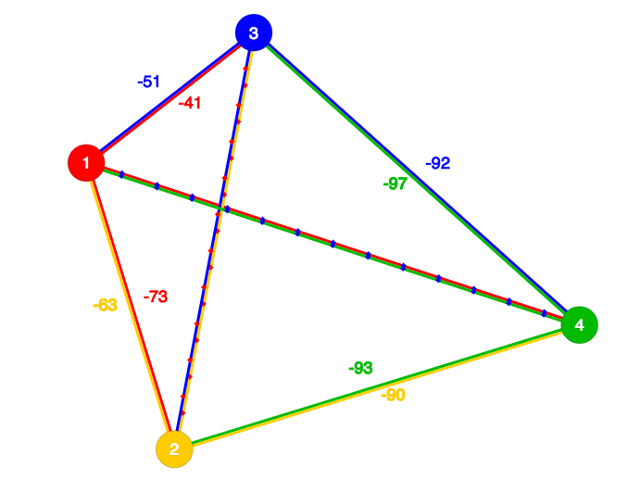
Each node attempts to communicate with every other node in the network, and in the process it keeps track of a routing table that describes which nodes it can talk to directly and which nodes that messages get routed through when there is no direct connection available. It also keeps track of the signal strength that it “hears” from a node when it communicates with it directly. The result is that each node has a data structure with this info. Here is a sample routing table (expressed in JSON) for node 2:
{"2": [{"n":1,"r":-68}, {"n":255,"r":0}, {"n":1,"r":0}, {"n":0,"r":0}]}
The data has an array of 4 records, one for each node in the network. The 4 records above represent the routing info for this node (2) communicating with nodes 1, 2, 3, and 4 respectively. Each record has two properties. Propery “n” is the identity of the node that node 2 must talk to in order to communicate with the node in this position of the table. Record number 1 {"n":1,"r":-68} means that node 2 can talk to node 1 via node 1. That is, it has successfully communicated directly with node 1 and the signal strength indicated by the “r” property is -68 dBm.
Record 2 {"n":255,"r":0} has an “n” value of 255 which means “self”, so we can ignore this record. Record 3 {"n":1,"r":0} means that node 2 must communicate with node 3 via node 1 because there is no direct communication (which is why the RSSI value is 0). Record 4 {"n":0,"r":0} has a “n” property of 0 which means that node 2 has not yet discovered a way to talk to node 4. This may because it has not tried yet, or perhaps node 4 has dropped out of the network and nobody can find it.
Over time, by attempting to send messages to every other node, each node builds up this information about who it can talk to and how its messages are being routed, as well as the signal strength that it “hears” from any node it successfully communicates directly with. The information sent in messages is the node’s routing table itself. That is why we represent the routing table as a JSON string and use abbreviated property names. We want the message to be short.
Visualizing the Mesh Network
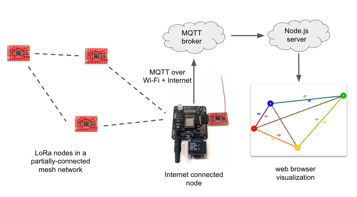
In order to display the network in a web page, we need to get all the routing information from each node. One of the LoRa nodes in my network (node 1) is connected to the Internet by connecting the Moteino board to an IoT Experimenter board. The IoT Experimenter is a simple ESP8266 development board I built to help with my IoT projects. It serves as a gateway to the Internet for this project. When node 1 receives a routing table from another node, it writes the JSON data over serial to the ESP8266 gateway code. The gateway writes the record to an MQTT topic. Over time, the routing table from each node is written to the topic and updated as the info changes.
Now we need a way for this information to be displayed on a web page. I wrote a Node.js server that subscribes to the MQTT topic and writes the info over a websocket to a web client using Socket.IO. The graphics are created using p5.js which is an easy way to draw impressive graphics on a web page canvas.
A solid line between 2 nodes means there is direct communication. The color of the line matches the node that is making the observation, and the number is the signal strength that the node “hears” from the other node. So below we can see that node 1 and 2 are directly able to communicate and that node 1 is receiving from node 2 with an RSSI value of -63 dBm and node 2 receives from node 1 with an RSSI of -64 dBm. The distance between nodes is proportional to the signal strength — you can see that node 4 is further away from the other nodes.
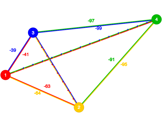
Lines with dots indicate indirect communication, for example, the lines between nodes 1 and 4 mean that they are communicating indirectly. The yellow dots on the red line mean that node 1 is communicating with node 4 via node 2 (which is yellow). The blue dots on the green line mean that node 4 is communicating with node 1 via node 3. Note that the communication between nodes 2 and 3 have red dots, meaning that node 1 is serving as the intermediary for these nodes.
Formation/Healing of a Mesh Network
Let’s see the visualization in action! This video shows the formation of a network when I connect power to the nodes. In the video I remove power from one of the nodes serving as an intermediary in the mesh and we can see how the network heals itself by finding new routes.
Get the Code
All the source code for this project is available on GitHub: nootropic design lora-mesh project.
It includes info on how to use this code yourself if you are interested.
Wi-Fi Camera Trap
Project source code at GitHub: wifi-camera-trap
We have lots of small wildlife around our house (mostly rabbits this year) and since I have a small camera module and a cheap PIR (passive infrared) motion sensor, I thought it would be fun to make a motion triggered wi-fi camera to deploy somewhere near the house.

Wi-Fi Camera Trap
The project is quite simple. If the PIR sensor is triggered, software on an ESP8266 wi-fi microcontroller captures an image using the ArduCAM camera module and uploads it to an image server. I wrote a very simple Node.js server that saves the uploaded images and makes them available on a gallery page for easy viewing. Nothing fancy.
Here are some of the great images we captured. The bunny’s movement triggered the PIR sensor with no problem!
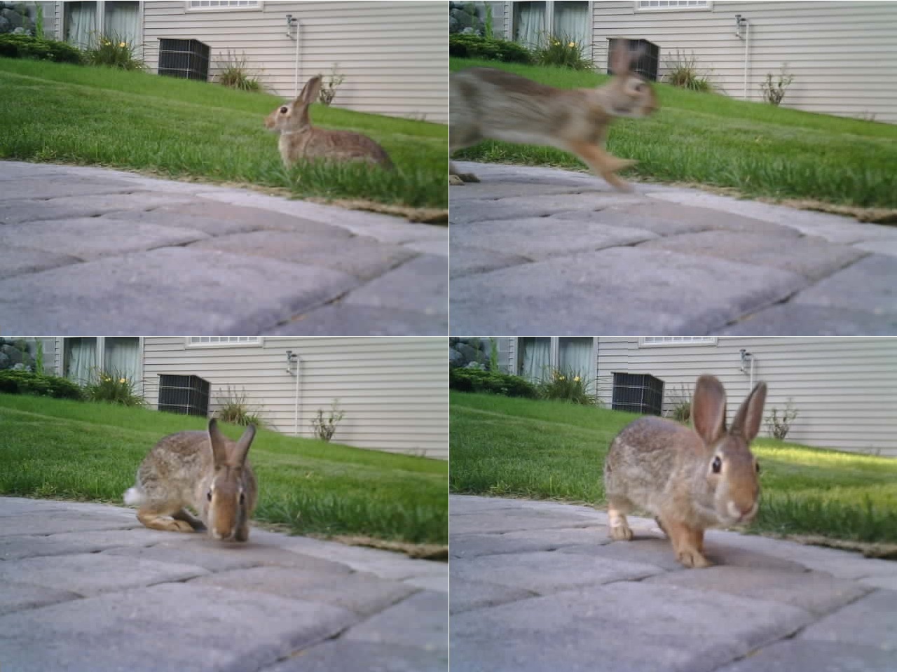
Bunnies over Wi-Fi
Inside the enclosure is an IoT Experimenter board that I designed to help me with my IoT projects. You can read more about it here. It has an ESP8266 wi-fi chip and connector for an ArduCAM module. I’m powering the whole device from a 5V battery pack. The IoT Experimenter is designed for input of 9V, but the onboard 5V regulator drops the 5V input down to about 4V, which is still fine for the camera module and PIR sensor in this project.
You can use any ESP8266 board you have. The camera connects to both the I2C and SPI pins, and the PIR sensor is connected to “Arduino pin 3” which is the RX pin on the ESP8266 but you can move it to any pin.
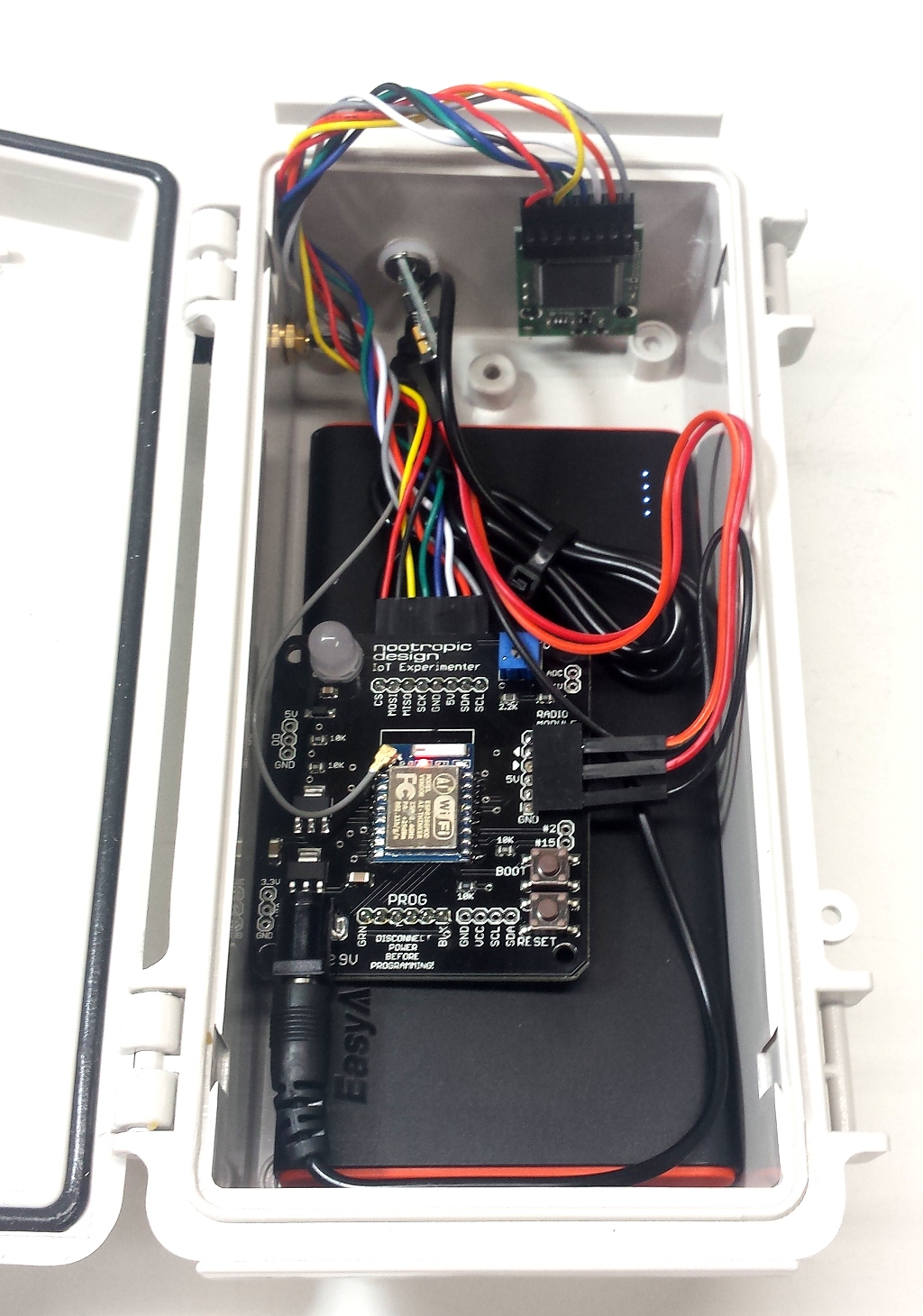
Wi-Fi Camera Trap – inside
Here’s what it looks like outside of the enclosure:
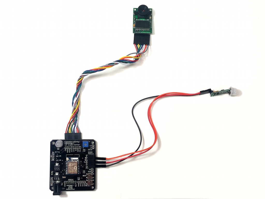
Wi-Fi Camera Trap Hardware
Here’s a closeup of the sensor. These are super cheap on AliExpress or Ebay. The output pin goes HIGH when there is new movement detected.
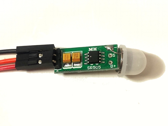
Cheap PIR Sensor
Software
I prefer to program ESP8266 chips using Arduino so I can take advantage of the hundreds of useful Arduino libraries. There’s plenty of information about using Arduino code on the ESP8266 here. This project uses the ArduCAM library control the camera module.
I’m also using the excellent WiFiManager library to make it easier to connect the ESP8266 to a network. Instead of hardcoding the SSID and password in code, if the chip can’t connect to any networks it already knows about, the WiFiManager will set up an access point (AP) named “CameraTrap”. Use your computer or phone to connect to the CameraTrap access point and a captive portal page will prompt you for your network name and password. If you aren’t automatically shown the captive portal page, just navigate to 10.0.0.200 and it will load.
After the CameraTrap code captures an image, it needs to upload it somewhere. I’ve provided a simple Node.js server for this purpose. The code POSTs the image to /upload on the image server which writes it to disk. You will have to specify the server hostname in the CameraTrap code. Note that the camera is actually installed upside down in the enclosure (so the wires fit) so my server rotates the image 180 degrees when it saves it to disk. On any machine where you can run a node server, type
node app.js
The server will run on port 8000. In any browser, just navigate to
to see the images. (Make sure you don’t accidentally include a trailing slash in the URL.)
All the software is available in the wifi-camera-trap GitHub repository. The Arduino code is in the CameraTrap directory, and the Node.js image server is in the imageserver directory.
Solar-Powered LoRa Weather Station
Project source code at GitHub: lora-weather-station
In this project I show how I built a remote, solar-powered weather station that transmits temperature and humidity readings over LoRa, and a base station that publishes the data to the Internet with MQTT (er, I guess we are supposed to say “cloud” now).
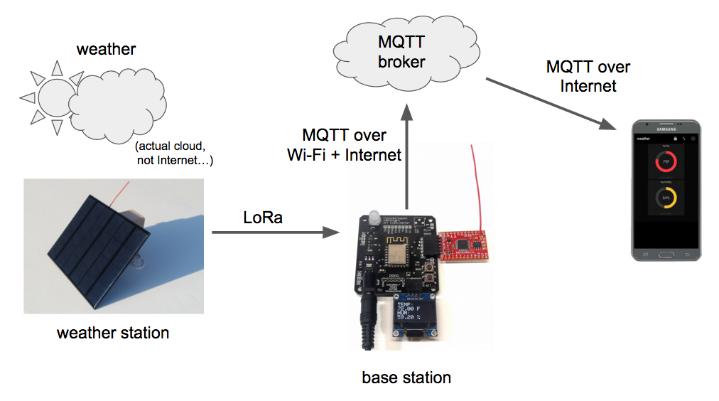
LoRa (Long Range) is a relatively new radio technology intended for reliable communication of small amounts of data over distances that are longer than achievable with bluetooth or Wi-Fi. It’s also geared toward low power applications. LoRa modules are relatively cheap (about $8 for a bare module), but the easiest way to use LoRa is to buy development boards that also have a microcontroller on them. Moteino and Anarduino MiniWireless both have LoRa enabled transceivers that work well and are essentially the same. Each is basically a small Arduino with ATmega328 and LoRa module. They cost around $20-25, and remember that you’ll need 2 of them, one for each end of the communication.
Weather Station
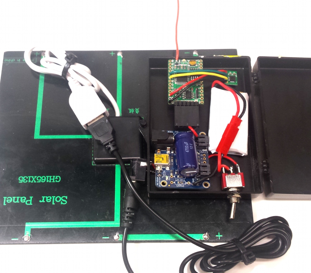
The remote weather monitoring station has a cheap solar panel, a LiPo battery, an Adafruit LiPo charging board, and an an Anarduino board with a TH02 I2C temperature and humidity sensor. I enclosed all of this in an small plastic box (not waterproof!).
Reading the I2C sensor is easily accomplished using this TH02 library. As for the control of the LoRa radio, there is a wonderful library called RadioHead that makes it easy to use all kinds of radio technology in embedded systems. For message format, I like to use JSON because it is easy to read and very flexible. The ArduinoJson is an excellent Arduino library for generating and parsing JSON strings. Using these 3 libraries, the Arduino sketch reads the sensor and transmits a small JSON message with the temperature and humidity readings to the base station every 10 seconds. The format of the JSON message is simple:
{
  temp: 72.1,
  hum: 54.2
}
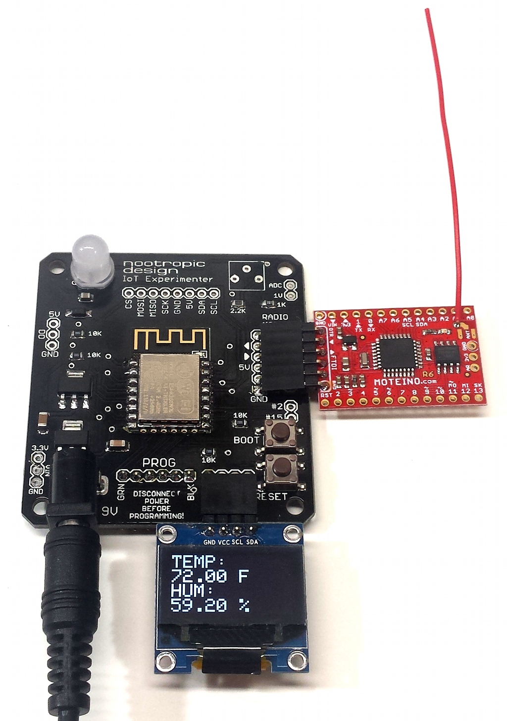
Base Station
The base station has 2 hardware modules. First, there is another LoRa module to receive the sensor reading messages. When the LoRa module receives the JSON message from the weather station, it simply writes the message over the serial UART which is connected to the second board, an IoT Experimenter development board. The IoT Experimenter has an ESP8266 WiFi microcontroller which provides a gateway to the Internet. I designed the IoT Experimenter as a simple tool for my IoT projects, and you can read more about the IoT Experimenter here. You can connect an OLED display which allows us to see the data right at the base station.
The code on the IoT Experimenter receives the message over serial and publishes the data using MQTT. In the source code for the ESP8266 you will need to add your WiFi user/password, as well as the info about an MQTT broker to publish the data to. You can set up a free account on CloudMQTT. Their free plan allows you to have up to 10 connections. The source code for this project makes it clear where to set the information for your account: username, password, server, and port. This project uses an SSL connection, so use the SSL port on your CloudMQTT server.
Instead of watching the weather data on the base station’s OLED display, it is more convenient to see it on the Internet or on your phone. I have an Android phone and use a simple app called MQTT Dash. It lets you create dashboards with controls on them. My weather dashboard has gauges for the temperature and humidity.
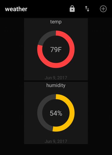
MQTT Dashboard on Android
Another way to see data from an MQTT broker is to use the Chrome app called MQTTLens. It allows you to connect to an MQTT broker, publish to topics and subscribe to topics. It works well.
Project source code at GitHub: lora-weather-station
