Forum Replies Created
-
AuthorPosts
-
philsaudio
ParticipantMichel:
I hope you see this post. Well I know very little about programming; and that did not stop me from diving head first into the Lumazoid you posted on Github…..many many thanks for posting it.
I am very familiar with where things are, wrote a serial port dump when in #debug compile. I am using Atmel Studio 7 so I can track into the library parts of the code and all sorts of stuff I learned so painfully about and do not comprehend.
By futzing around I could get it to do 144 LED but something about going higher is not working for me. If you could make a deposit of Lumazoid on Github that does 300 LED’s maybe I can reverse engineer that.
Again thanks for the customer support Michael.
philsaudio
ParticipantI have a 12V LED strip. It is basically one WS2811 controller chip to three RGB LEDs in series, which is how they drop the voltage for the RGB chips. The 24 bits shifted into the WS2811 is displayed in all three series LED and constitute one address on the strip. Therefore a 300LED strip looks like a 100 LED strip to the Lumazoid code.
I wired this onto my own PhilduinoZoid (and arduino board running the lumazoid code from github) The onboard VR supplied the 328P ( I may have had to remove the power reversal protection diode to get and extra 0.5VDC on the VCC, maybe even the 5v regulator to because it is in 328P VCC circuit when powering from the barrel connector) with 5V. Then I connected the strip power to the barrel connector tab going directly to the 12VDC power supply. The digital drive from the Arduino 328P was plenty for the strip data line and the 12VDC no problem for the Arduino.
Since the factory Lumazoid does not have the Voltage Regulator you may be able to get the with the factory Lumazoid to power a 12V strip.
NOTE: I have not tired this. Perhaps if you had a 5v supply going to the factory Lumazoid (like the USB input) and put 12V to the 12V strip and strapped the grounds you could get it to work.
philsaudio
ParticipantIn a companion thread I posted pictures of the circuit path I used to put mic audio directly into the A/D pin on the Atmel 328P.
I used a ten cent ebay electret mic and the shown $5 ebay “Max 1498 leveler” board.

If you look closely next to the + output pin you will see where I shorted across the decoupling pin so DC is input to the A/D converter. I tried several modules before settling on the pictured one. The cheepo’s are knock sensors and will not work well. Some of the ones with compressor chips work, but the one shown works best for my projects.
PS: I hope the pictures and links work because if IRRC this forum does not allow edits.
philsaudio
ParticipantWhen designing the microphone interface for my philduinozoid I scoped the pin on the Lumazoid Atmel 328P with the music on it. The signal on the pin needs to be very robust, actually clipping. The signal needs to float at 1/2 VCC and clip at 5v and 0Vdc to work best.
That is the signal on the microprocessor pin. The signal into a factory Lumazoid 1/8″ input jack needs to be robust. I drive mine with a headphone amp made for the studio, IE blow your ears out loud so you can hear the guide track over your drummer and guitar player loud. Works great. IMHO a phone output is a little too weak for the factory Lumazoid.
philsaudio
ParticipantYou know, it is so hard for ME to use this forum, and putting images up is so difficult, and the inability to come back and edit after a couple of minutes, I give up on sharing this project. It would have been good.
Thanks for the code Michael, I could not do that in a hundred years. Without being able to post pictures I can not tell my story.
The above link is to my youtube of the prototypes.
-
This reply was modified 7 years, 7 months ago by
philsaudio.
-
This reply was modified 7 years, 7 months ago by
philsaudio.
philsaudio
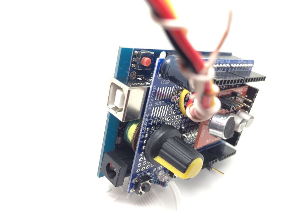
ParticipantHere is what my first “AcousticDuinoZoid” prototype looks like. I will give more details on construction and design decisions but first a look. I mounted the Mic, Mic preamp/leveler, buttons and a pot to the shield. On this one the strip is powered from the Arduino 5v Regulator so the JST connector is soldered to the shield.

This is the PhilDuinoZoid shield top side.

This is the PhilduinoZoid (prototype 1) shield bottom side.

-
This reply was modified 7 years, 7 months ago by
philsaudio.
-
This reply was modified 7 years, 7 months ago by
philsaudio.
-
This reply was modified 7 years, 7 months ago by
Michael. Reason: fixed image links
philsaudio
ParticipantI guess what I discovered jumping the audio from the production board to my Auduino Uno with the Lumazoid code running is; the 328P wants to see a very hot signal, 5vPP, almost if not very much clipping.
-
This reply was modified 7 years, 9 months ago by
philsaudio.
-
This reply was modified 7 years, 7 months ago by
-
AuthorPosts
