Wireless Robotics Platform with XBee Remote Control
Difficulty Level = 7 [What’s this?]
I built a remote-controlled robotics platform using a 4WD mobile platform, an Arduino (Seeeduino Mega), an Adafruit motor shield, and two XBee radios for communication. There are also some super-bright white LEDs on the front for headlights. The point of the project was to show how an XBee radio can be used to send joystick sensor data without using a microcontroller on the remote.


The vehicle is very easy to control using a joystick and a couple of buttons to control the lights. First I’ll describe how the remote control unit works, then I’ll show how the vehicle was built.
The Remote
Here’s a picture of the remote control unit that I built on a breadboard. A Parallax joystick is used to control the vehicle, one button turns the headlights on/off, and another button puts the headlights in “scanner” mode, you know, like Kitt or like a cylon. The radio requires a 3.3V supply, but the analog pins cannot take more than 1.2V, so I used some precision resistors to form a voltage divider so that the analog input voltage was stepped down to less than 1.2V. Also note that the joystick is rotated 90 degrees so that it worked on a breadboard with this orientation.

To make this work, one radio needs to be running the “coordinator” firmware, and the other running the “router” firmware. In this project, the coordinator is on the vehicle and the router is on the remote control, but it should not really matter. It’s important that each radio be running the API mode firmware, not the AT/transparent firmware.
I used the X-CTU tool from Digi to write the appropriate firmware to the radios and configure them. If you have not done this before, this is not a good project to start with. It is best to start with 2 radios that you already have working together using the API firmware.
The XBee on the remote control unit is configured to send analog/digital sample packets every 100ms. Pins AD1 (pin 19) and AD2 (pin 18) are configured as analog inputs and are connected to the potentiometers in the joystick. Pins DIO3 (pin 17) and DIO4 (pin 11) are configured as digital inputs for the two buttons on the remote that control the lights on the vehicle. Here is a list of the configuration parameters that were set on the remote radio:
- AD1/DIO1 = 2 (configured as analog input)
- AD2/DIO2 = 2 (configured as analog input)
- AD3/DIO3 = 3 (configured as digital input)
- DIO4 = 3 (configured as digital input)
- IR = 0x64 (sample rate set to 100ms)
- PR = 0x1FFF (all pullup resistors enabled — this is the default)
This is a schematic of the remote control unit:

The Vehicle

The wiring for the vehicle is fairly simple. Inside the 4WD platform are 5 AA batteries for powering the motors, and a 9V battery for the Arduino. I’m using a Seeeduino Mega because that’s what I had handy but any Arduino will work. The Adafruit motor shield is connected to the 4 DC motors inside the chassis. I used the 3.3V power supply on hte Arduino to power the XBee radio. The TX/RX lines of the radio are connected to the RX/TX pins on the Arduino. There’s a ribbon cable connecting 4 output pins to the LED headlights, and a ground wire running to the headlight assembly. Here is the bottom of the headlight assembly. These are 100 ohm resistors to keep the current draw below 20mA per LED.

The Software
This code depends on the Adafruit library for using the motor shield, so download that and install it as an Arduino library. The Arduino sketch for this vehicle RobotVehicle.zip can be downloaded from here. Read the code for an explanation of how it works. The basic idea is to decode the incoming XBee API packets and map the joystick position information to the motor speeds. If the joystick is forward, all four wheels move forward. If the joystick is turned slightly to one corner, then the vehicle will move along an arc. If the joystick is hard left or right, then the wheels on the left side and right side will turn in opposite directions, causing the vehicle to rotate in place. By studying the code carefully, you should be able to understand how all of it works. Enjoy!
Displaying Android Phone Video on an RGB LED Matrix
Difficulty Level = 10 [What’s this?]
I bought this awesome RGB LED matrix panel from Adafruit and really wanted to see if I could make it display video from an Android phone. It was somewhat difficult, but by using my Android phone, the OpenCV computer vision library for Android, a Sparkfun IOIO board, and an Arduino, I got it working.

All of the hardware and software setup details are below, but before I explain how it works, let’s see it in action:
How It Works
This is not a beginner project, so if you don’t have experience doing any Android development, you’ll need to be patient. Just getting your Eclipse development environment set up for Android development with the OpenCV and IOIO libraries took me a couple of hours, and I’ve been using Eclipse for about 10 years.
An Android app running on the phone captures video frames and processes them down to a lower resolution suitable for the 16×32 LED matrix. OpenCV is a powerful computer vision/image processing library, and there’s a version that runs on Android. I used the OpenCV library to convert the video frames to 16×32 pixel resolution to match the LED matrix. I also constrained the color space of the frames to 12 bit color. That is, each pixel has 4 bits each for red, green, and blue. That means that each pixel can have 16 different brightness levels of red/green/blue, yielding 4096 possible colors. In other words, all of the image processing is performed on the phone because it’s much more powerful than the Arduino.
The 16×32 12-bit image uses 1024 bytes of memory on the phone (2 bytes per pixel). The Android then uses the IOIO library to write this data out one of the IOIO board’s serial ports. Each frame starts with a two-byte frame marker 0xF0 0x00, then the bytes for the pixel values are written. The performance bottleneck is between the phone and the IOIO board. I can only write about 4 frames per second, even though the serial interface between the IOIO and Arduino is 115200 baud. Since each pixel really only needs 1.5 bytes instead of 2, I could pack the pixel data tighter to get perhaps one more frame per second, but didn’t think it was worth the trouble.
The green wire in the picture below is a serial connection from the IOIO and Arduino. The Arduino code simply reads the pixel values, using the frame marker to know when a new frame begins. The pixel values are written to the LED matrix panel using the Adafruit library for controlling the panel. Driving this matrix is no small feat for the Arduino, since the matrix panel does not do any PWM on its own; the Arduino needs to generate the PWM. This matrix driver software could have been written for the IOIO to control the matrix directly without an Arduino, but Adafruit had really tuned this library for high-performance and very precise timing, so I thought I’d better stay with the Arduino code for now. The result is video at about 4 frames per second. Not very fast, but the color rendition is pretty good.
Hardware Setup

The RGB matrix panel is wired to the Arduino just as Adafruit’s instructions describe. They have an excellent page that describes how the panel works and how to use it.
The RGB matrix and the Arduino are powered by a 5V regulated power supply that can provide 2A (also from Adafruit). The IOIO board is powered independently by a 9V supply that can provide 1A. It’s important to provide plenty of current to the IOIO board so that the phone can charge, however you can adjust a potentiometer on the IOIO to reduce the charging current. As with any project with multiple power supplies, all the grounds must be connected. A single green wire provides the serial data feed from the IOIO to the Arduino RX pin.
I used a diffuser in front of the display to make it look much better. Without a diffuser, the LEDs are simply blinding and it’s not easy to see any image. My diffuser is a piece of acrylic with paper vellum on it. The diffuser is held about 5mm in front of the LED panel (with a little roll of duct tape as a spacer).

The phone (a Samsung Nexus S) is connected to the IOIO via USB. I mounted above the panel by holding it very gently with a Panavise.

Software Setup
Android + IOIO + OpenCV Software
The hardest part of the software setup is preparing your development environment for Android, IOIO, and OpenCV development. The details of how to do this are beyond the scope of this article, but all of the steps are documented in various places.
- Set up your Android development environment: this is documented on the Android SDK website. After you have performed this step, you will be able to write simple Android programs and run them on your phone.
- Install the IOIO library: see this great Sparkfun tutorial which describes how to run Android apps that communicate with a connected IOIO board. After you have performed this step, you will be able to upload the HelloIOIO app to your phone and have it communicate with your IOIO board. Don’t move on to the next step until you are sure you have the IOIO working with your phone.
- Install the OpenCV library for Android by following these instructions. After successfully doing this, you should be able to run the OpenCV Android examples on your Android phone. Don’t proceed until you have this working successfully.
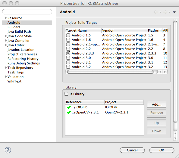
- Now that you have all the supporting libraries in place, download the RGBMatrixDriver Android application project and install it in your Eclipse workspace and open it. With luck, it will compile cleanly. If not, make sure that the project is correctly pointing to the IOIO and OpenCV libraries as in the image below.
- You may need to customize the code a bit. I used IOIO pin 7 to send serial data to the Arduino, so you may need to change the pins specified in the call to
openUartinRGBMatrixActivity.java. You may also need to change some screen dimensions specified inRGBMatrixView.javato work with your phone — just follow the comments.
Once you have the application running on your phone, this is what it looks like in action. The video image is displayed with the same resolution and colors as the RGB matrix.
Arduino Software
Now that the hard part is done, it’s easy to get the Arduino software installed.
- First, you’ll need Adafruit’s library for driving the panel. This project uses a slightly older version which you can find here. Install it in your Arduino sketchbook libraries folder just like any other library.
- Then download and install the
RGBMatrixSerialsketch and install it in your Arduino sketchbook. Compile it and upload it onto your Arduino. The sketch is so simple, I’ll show the whole thing here:#include "RGBmatrixPanel.h" #define A A0 #define B A1 #define C A2 #define CLK 8 #define LAT A3 #define OE 9 #define WIDTH 32 int count = 0; byte currentByte = 0; byte lastByte = 0; uint16_t color; RGBmatrixPanel matrix(A, B, C, CLK, LAT, OE, true); void setup() { Serial.begin(115200); matrix.begin(); } void loop() { int index; while (Serial.available()) { lastByte = currentByte; currentByte = Serial.read(); // Look for the frame marker 0xF000 if ((lastByte == 0xF0) && (currentByte == 0x00)) { count = 0; matrix.swapBuffers(false); } else { if ((count % 2) == 1) { color = (lastByte << 8) | currentByte; index = (count-1)/2; matrix.drawPixel(index % WIDTH, index / WIDTH, color); } count++; } } }
Future Ideas
- increase the framerate a bit by packing 2 pixels in 3 bytes of transmitted data (only really need 1.5 bytes per pixel), but need different frame marker detection.
- use the 32x32 matrix panel from Adafruit
- try BlueTooth connection between phone and IOIO board (need to upgrade IOIO firmware)
- Get an Arduino Mega ADK and use it to interface with the Android phone instead of the IOIO. The framerate should be higher.
Vintage Holiday Ads for Our Kits!
Here are our new holiday ads for some of our kits…show your friends! Click through for product info! Buy!


chipKIT Uno32 Review: Arduino Compatible?
I recently got a chipKIT Uno32 prototyping platform from Newark so I could take it for a spin. Newark is the US distribution arm of Farnell and they carry both the chipKIT Uno32 and the chipKIT Max32.

Nice looking board!
The chipKIT boards are manufactured by Diligent and claim compatibility with Arduino boards. The Uno32 is similar to the Arduino Uno, and the chipKIT Max32 is similar to the Arduino Mega, but they are both based on Microchip PIC32 microcontrollers. The Uno32 that I have has a PIC32MX320F128H microcontroller.
There are plenty of powerful features of the Uno32 that make it compelling, especially when comparing to the Arduino. There are 42 I/O pins, which is nice. The clock speed is 80MHz versus 16MHz on the Arduino. For most hobbyists this won’t matter much; I have not often found CPU speed to be a limiting factor in projects. There’s more Flash memory to store your programs: 128K versus Arduino 32K. Again, I have never felt limited by the size of a program. In fact, the largest Arduino program I’ve written is a full-featured implementation of Asteroids and this only took 28K of Flash memory for the program.
But when it comes to SRAM, the memory that you use in your programs to store data structures, buffers, stack, etc, the chipKIT Uno32 has 16K versus 2K on the Arduino. This is a vast improvement for me. I’ve done a lot of video work with the Arduino (e.g. the Video Experimenter shield, Hackvision game system, etc.) and the size of SRAM is a significant barrier to video frame storage.
There are also 2 UARTs used for serial communication, versus the 1 on Arduino. When using Arduino, if you want to communicate with two serial devices at once (for example, the Serial Monitor on your computer and a GPS module), you had to use a software implementation of serial communication for one of the devices. But with 2 UARTs, the chipKIT Uno32 allows 2 independent hardware implementations. I like that a lot. There’s also a realtime clock and calendar (RTCC) on the PIC32MX320F128H microcontroller with the option of connecting a 32.768KHz clock crystal. That could be useful for some projects.
Make sure you check out the Hackaday article where they did an in-depth review of these boards from a performance perspective.
But what I was really interested in understanding is Diligent’s claim that the chipKIT boards are “Arduino Compatible”. What does this mean in practical terms for the hobbyist?
Compatibility: The Good News
Well, you can program the Uno32 using the normal Arduino API, like digitalWrite, digitalRead, analogRead, etc. For most hobbyists, this will allow them to read sensors, light LEDs, control motors, and the like. Maybe you need lots of digital outputs — the Uno32 has 42 pins instead of 19 on the ordinary Arduino. The Uno32 is a lot cheaper than the Arduino Mega.
So, the normal Arduino API works, but what about direct access to ports in order to more efficiently control digital I/O? I often use direct manipulation of the AVR microcontroller ports instead of using digitalWrite and digitalRead calls. That is, I set a digital pin HIGH with something like PORTB |= 0x2 instead (for speed). Will this code work with the chipKIT boards? Yes! I was surprised, but apparently the chipKIT compiler makes the appropriate adjustments to the resulting compiled code to allow direct port manipulation using the AVR semantics.
Compatibility: The Bad News
Here are some things that I think are bad news with regard to Arduino compatibility.
- Outputs are 3.3V — This means that the output voltage of the digital pins isn’t high enough to be recognized as an input HIGH voltage by many 5V CMOS chips. For example, you can’t use the digital outputs on chipKIT boards to drive a 74HC595 shift register. The 3.3V output is not high enough to trigger the input pins on CMOS chips which generally require at least 3.5V. This problem can be address by adding more components to your circuits (e.g. a transistor to translate to a higher input voltage), but that defeats the purpose of convenient Arduino shields.
- Current limitations — On the Arduino, each digital pin can source/sink up to 40mA as an absolute maximum, but in practice you should limit to 20mA. However, the chipKIT boards have a maximum of +/-18mA per pin, and the reference manual states that this should be limited to +7/-12mA per pin. This is going to be a disappointment to people wanting to drive LEDs, 7-segment displays, etc. Furthermore, the maximum current that can be sourced/sunk across ALL I/O pins simultaneously is only 200mA. That’s not much current to spread across 42 pins! I tried to light a bright blue LED and was only able to draw a dim 8mA (with no current limiting resistor at all!) because the forward voltage of the LED is just barely over the 3.3V board output voltage. Again, this can be solved with external circuitry, but that’s not convenient.
- Code rewrites — If your Arduino code accesses AVR registers directly (for example to use timers) or involves AVR assembly, you are going to have to rewrite it. This means that using my Video Experimenter on the chipKIT board would b e a total rewrite of the gnarly AVR assembly.
- Incompatible pin assignments — If you use special microcontroller functions found on the AVR, you will not find them on the same pins on the chipKIT boards. For example, my Video Experimenter shield utilizes the analog comparator function to compare the voltage of a video signal with a reference voltage. The analog comparator pin is D6 on the Arduino, but is D11 on the chipKIT Uno32. This is another barrier to using Arduino shields on the chipKIT boards. The pins don’t have the same functions.
Bottom Line
The chipKIT Uno32 is a nice board and will give many Arduino users a boost in speed and in the number of pins available. Users doing more sophisticated things that involve direct AVR register access, timers, and libraries written in AVR assembly won’t be able to simply switch to the chipKIT for their work without a lot of rewriting. Most disappointing to me is that many Arduino shields simply aren’t going to work on the chipKIT. And due to the 3.3V output, even projects using LEDs (the bread-and-butter of the Arduino world!) may have some challenges due to current limitations and the lower voltage available to light up all those blinky lights. Nonetheless, I welcome Microchip and Diligent’s efforts and hope to see some great chipKIT projects in the future!
Resources
Diligent chipKIT site
chipKIT Uno32 Reference Manual
chipKIT forums
Tips and tricks for translating between 3.3V and 5V
Watching the Feds Watch Me
I recently showed my Defusable Clock project on this blog. It got a lot of attention on the usual techie/hacker blogs, and the reaction was generally positive. I plan on selling an electronics kit so people can build their own, but I had reservations about doing so because some people might do something stupid with it. Writing about the project allowed me to get feedback about whether it was a good or bad idea. I concluded it was probably not a bad idea as long as I didn’t sell it pre-assembled, and didn’t sell anything that looked like explosives. I really don’t want to do anything wrong or enable anyone to do anything wrong. Just electronics fun.
A few days later, on Friday September 9, I noticed an interesting lurker in my online store. The domain name of the potential customer caught my eye: tsa.dhs.gov. Was this someone at the Department of Homeland Security? Specifically, the Transportation Security Administration?

Who's this shopping in my store?
I used an IP lookup tool to check the IP address for 216.81.80.134. Sure enough, it was Homeland Security. That was easy.

IP address lookup confirms that the shopper is from DHS
This isn’t the kind of attention I want. I decided to check my Google Analytics console to see if I could learn anything about who was visiting my site that day. One of the things you can look at is the service providers that your visitors are coming from. This isn’t usually very interesting, because it’s just Comcast, Verizon, etc. But this day was different. I was absolutely shocked to find that over 5% of my traffic was coming from one location.

Over 5% of my visitors on Sept. 9 were from Department of Homeland Security
That’s right — dozens of distinct visitors were from Homeland Security, and the number was rising steadily. By mid-day over 100 people at Homeland Security had hit my site.
Uh oh.
I had not done anything wrong, but I really didn’t want a personal visit from Homeland Security, the FBI, or SEAL Team Six. In late morning, my wife called me at the office from home — I was sure that gentlemen in dark suits were at the door, but it was a false alarm. I was feeling paranoid.
Could the government really be that interested in me? Maybe looking at a map of my U.S. visitors would make me feel better…

Nope.
The statistics indicated that the visitors were not spending more than a minute on average on the site. They were taking a quick look, then leaving. My theory is that maybe a link to my Defusable Clock was included in some morning briefing or something, and a bunch of people checked it out. What do you think?
Nonetheless, I felt compelled to add this paragraph to the clock project post, hoping it might defuse the situation (pun intended):
Dear friends at the U.S. Department of Homeland Security:
I can see from my logs that you are very interested in my project, but I assure you that this is just a clock. There is nothing dangerous in these photographs; just wooden dowels and clay. I sell DIY electronic kits for customers to assemble themselves, and plan to sell the electronic components for this clock as a kit. It is no more dangerous than any other alarm clock. I would never sell or ship anything that looks like a dangerous substance or device as shown in the photos below. I’m on your side. So, we’re cool, right?
The hits from DHS came to a stop around 4:30pm EDT as government employees headed home for the weekend, so I started to feel better. Their visits declined over the 9/11 weekend and were a mere trickle this week. I successfully flew to NYC yesterday (Thursday the 15th) to attend World Maker Faire this weekend. If you see me at Maker Faire, make sure to come up and say “glad you made it!”. I’ll be wearing this shirt with an image of my Video Experimenter board design. See you there (hopefully)!
