Project source code at GitHub: samd21-lora-gps
I’ve been doing some LoRa projects lately in order to learn as much as I can about this exciting new radio technology (see this LoRa mesh networking project and this LoRa weather station). ATmega328-based Moteino modules work great for a lot of projects, but I wanted a LoRa node with more processing power, more memory, and an onboard GPS receiver. The ATmega328 is just too constrained with memory — I’ve outgrown it. I really wanted a LoRa board with an ARM Cortex microcontroller like the SAMD21. This is the microcontroller used on the Arduino Zero. So, my ideal board is a SAMD21 with LoRa radio module and GPS receiver, all programmable with the Arduino IDE.
But, where is such a board? I could not find one so I decided to design and make one myself.
Hardware Design
Microchip/Atmel makes a SAMD21 chip and there are several variants. Most designs use the ‘G’ variant, but I wanted to use the simpler ‘E’ variant because it comes in a TQFP-32 package that I can very easily solder in my reflow oven without any trouble, or even by hand if I have to.
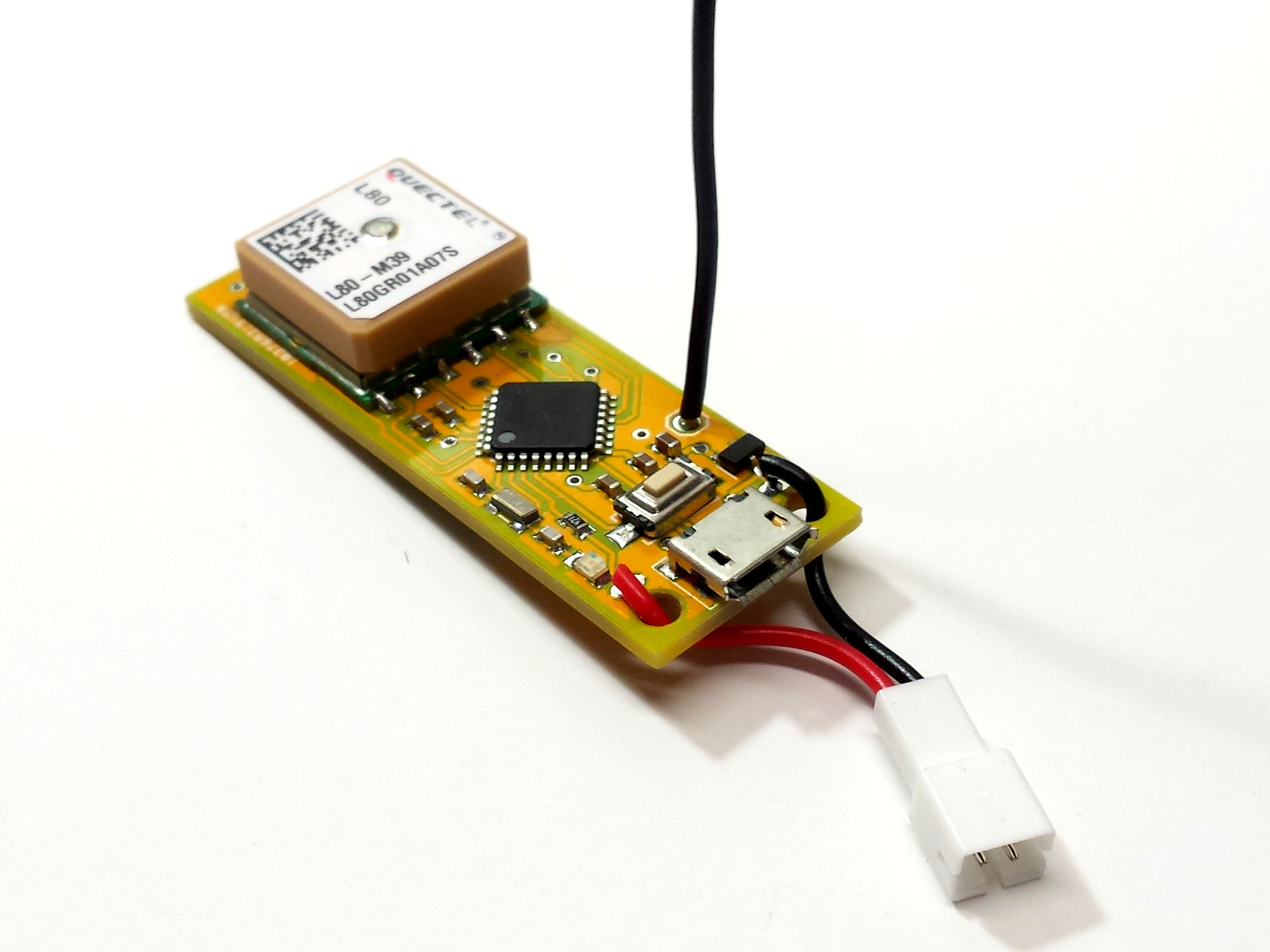
The GPS module is a cheap Quectel L80 with a MTK3339 chipset. It is easy to use but the backup power circuit requires a charging circuit, so I don’t have battery backup for quick startup. I mainly chose this module because it has big soldering pads with 2.54mm spacing for easier prototyping.
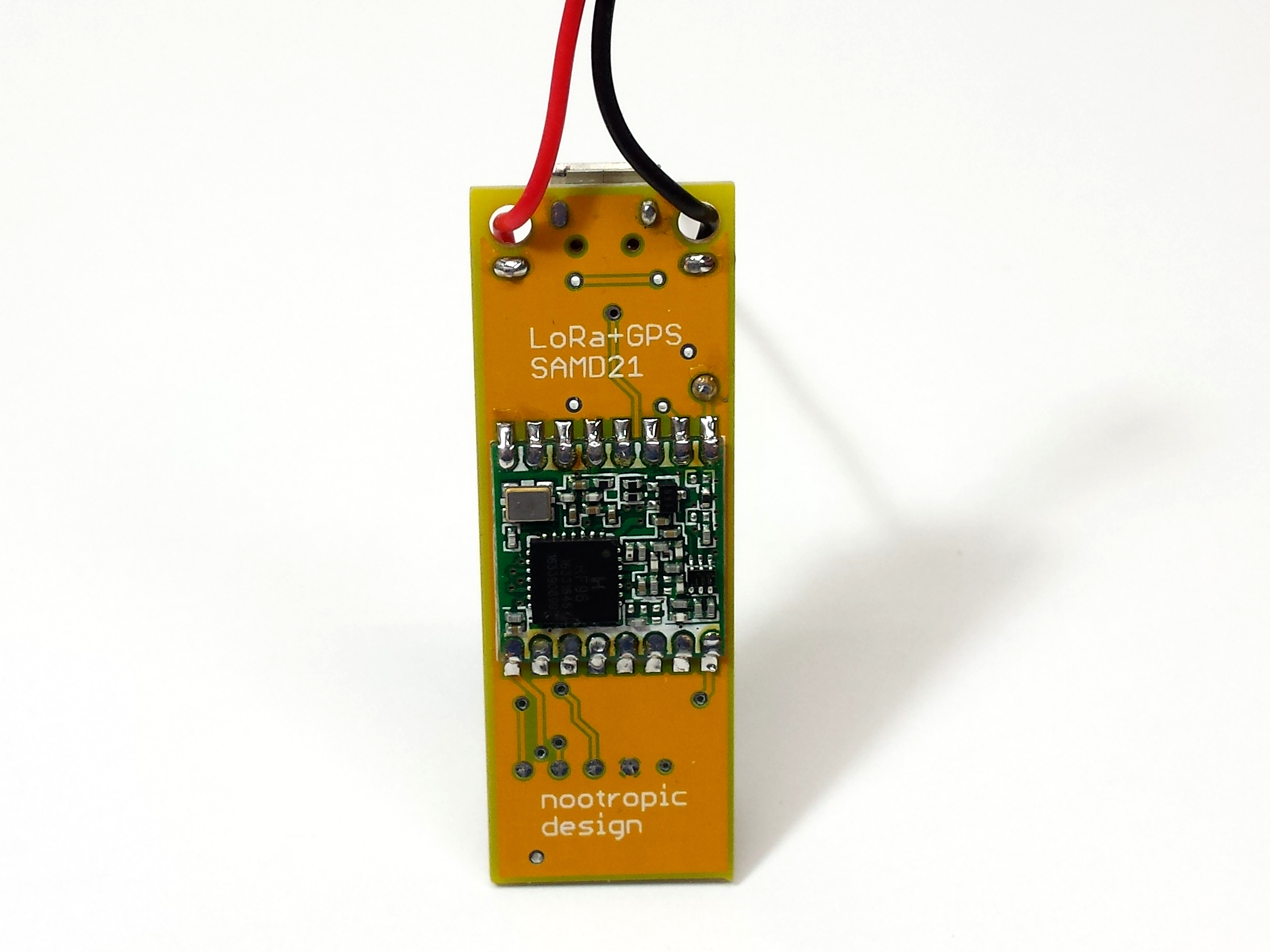
The LoRa radio module is a HopeRF module soldered to the bottom of the board.
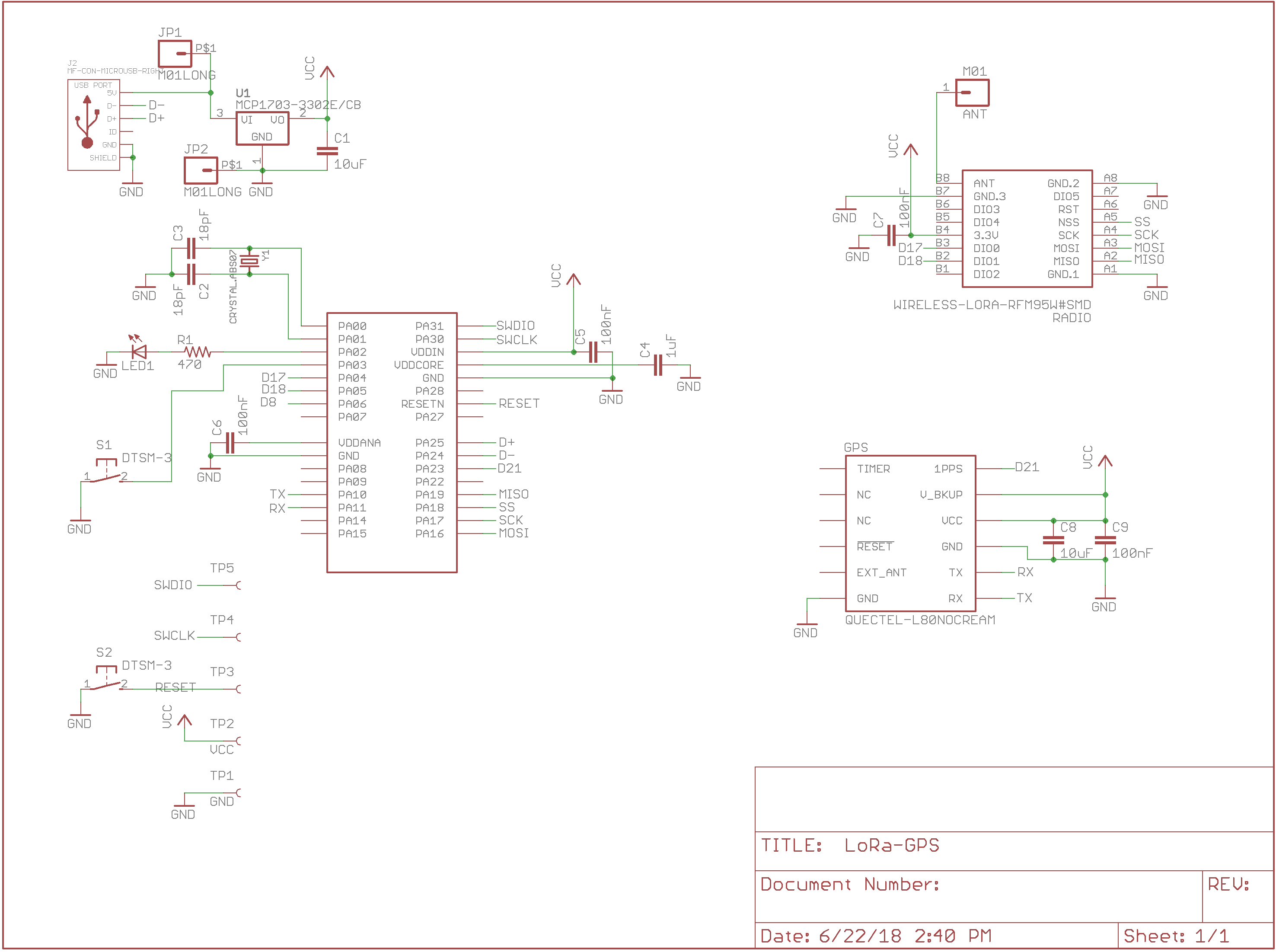
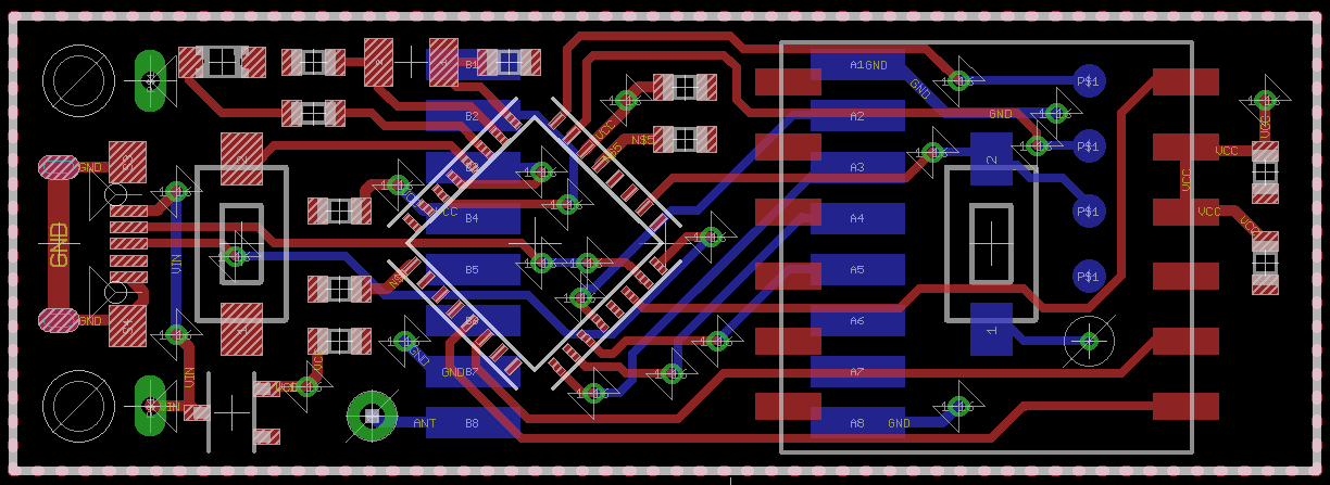
Here is the schematic and image of the board design. The Eagle files are in the hardware directory of the samd21-lora-gps GitHub repo.
Burning a Bootloader
To make this board work with Arduino, I had to burn the Arduino bootloader onto the chip using an Atmel-ICE programmer. My board has 5 test points on the bottom for this purpose. The Atmel-ICE needs connections for VTG (3.3V), SWDIO, SWCLK, RESET, and GND. The board has to be powered over USB during the programming procedure. In the Arduino IDE, I selected Tools->Board = Arduino/Genuino Zero (Programming Port), Tools->Programmer = Atmel-ICE, and then just clicked Tools->Burn Bootloader. In a few seconds, my board had a bootloader and is now programmable as an Arduino Zero!
Programming the Board
I was careful in my design to allow this board to be used as an ordinary Arduino Zero even though it uses a different variant of the SAMD21 chip. The downside of this is that the default SPI pins defined for the Arduino Zero board use pins that are not present in the ‘E’ variant of the SAMD21. Luckily the design of the Arduino system is flexible enough that we can define a different SPI interface on different pins. There is a great article by Adafruit on this topic but it may be pretty hard to understand. The bottom line is that by using these lines in your Arduino sketch:
SPIClass SPI1(&sercom1, 12, 13, 11, SPI_PAD_0_SCK_1, SERCOM_RX_PAD_3);
pinPeripheral(11, PIO_SERCOM);
pinPeripheral(12, PIO_SERCOM);
pinPeripheral(13, PIO_SERCOM);
You can now use interface SPI1 to communicate with the LoRa module. I wrote a simple test sketch that reads the GPS module and broadcasts the GPS coordinates on the radio every 15 seconds. See the samd21-lora-gps GitHub repo.
This test code uses the RadioHead library to control the LoRa radio. The RadioHead library is flexible so I was able to use the SPI1 interface by defining a couple of new files, RHHardwareSPI1.[cpp,h].

More memory? So, this might be able to plug a gap in the lorawan/gps market nobody seems to be bothered about, or bothered enough about anyway.
use case : At “base” there is lorawan gateway. When “tracked item” leaves base, connectivity is lost. When item returns to base, it sends that days’ gps coords to the gateway (think: 1 coord per hour).
Seems a simple enough request, but nobody wants to make such a thing – I know I can get a quite a few coords (albeit a greatly reduced “sentence”) into the flash mem of pro-minis, so this should be a better candidate, no?
Could you please break out any unused I/O pins somewhere? That would make this much more useful.
If it were a product, I would break out pins. But for my own use, I wanted it small.
How much did this cost to build? There’s another product that uses this setup called Lynq on Indiegogo. They were $220USD for 2.
About $30 in parts to make it. LoRa module is $8, GPS receiver $11, PCB, microcontroller, etc. Not cheap, but not as expensive as the Lynq on Indiegogo. I’m skeptical of the Lynq. It doesn’t say that it uses LoRa technology at all. It must be some proprietary protocol on an ISM band. I only pay attention to crowdfunding campaigns if they actually deliver, and Lynq is not delivered.
I might try to build one. I can’t wait for the Lynq to ship sometime next year. I saw somewhere that they said they are using LoRa. It might be in the FCC report for their test units.
Where did you get the lora and gps modules?
The GPS modules are from AliExpress. They are Quectel L80 modules.
The LoRa modules are HopeRF RFM95W 915MHz modules. A company called Anarduino sells them. They have an EBay store: https://www.ebay.com/str/anarduino/
I want 4! please can you sell it in Tindie or similar or publish full BOM and instructions to make it at jlcpcb or … something? I really need this, but i can’t pay for the indiegogo thing. And other questions, the usb charges the battery?
I’m afraid I don’t have time now to produce this as a product. The design files are available: https://github.com/nootropicdesign/samd21-lora-gps/tree/master/hardware
No, there is no charging circuit for battery.
Hi
I imported the hardware files to Altium Designer, redesigned the layout for better RF and EMI performance. Also added inner layers, now become 4 layers.
I will try to make it works too. (I hope)
Nice!
Me again :) ok, i suppose that i have to do is:
1- upload the eagle file to an online service that develop the board
2- Solder the radio and gps modules
3- solder the other components (where are them?)
4- flash arduino on it
can you confirm it? Thanks!
Yes, that would be the steps. If you are in the US, I can send you a few boards already made. You would need to add the components. You also need an Atmel ICE programmer to flash the Arduino bootloader. An ICE programmer is expensive, I’m afraid.
If you are in the US, contact us over email.
Where do you order this PCB assembly? I’m searching for a long time a reliable PCB Assembly company, but I have not got find it!!!
I assembled these myself with my own reflow oven. But I use ITEAD Studio in China for mass production of my products. They are good.
Hi,
I am new to LoRaWAN. Can you give me the steps to add your module to thethingsnetwork?
Thanks
Best regards,
Francisco
See these articles about The Things Network:
LoRaWAN Networking Part 1: The Gateway
LoRaWAN Networking Part 2: Using End Devices
Hi,
one more question, what kind Antenna have you used for LoRaWAN connection? I see only a cable in your first picture.
Thanks
Best regards,
Francisco
It’s just a wire antenna. It’s black in the picture. A 78mm (quarter wavelength of 915MHz) antenna works very well.
I am in Europe. 868 MHz. What would be the optimum cable length?
https://www.thethingsnetwork.org/forum/t/antenna-length-for-868-and-433-mhz/5378
Thanks for your replies. i have assembled pcb as you have descripped. With Atmel-ICE I have activated as Arduino Zero. Then I have tried to upload your sample code “LoRaWANTestOTAA”. I am getting this error. LED id blinking on the board. What can I do now?
Sketch uses 52600 bytes (20%) of program storage space. Maximum is 262144 bytes.
Forcing reset using 1200bps open/close on port COM37
PORTS {COM1, COM37, COM39, } / {COM1, COM37, COM39, } => {}
PORTS {COM1, COM37, COM39, } / {COM1, COM37, COM39, } => {}
PORTS {COM1, COM37, COM39, } / {COM1, COM37, COM39, } => {}
PORTS {COM1, COM37, COM39, } / {COM1, COM37, COM39, } => {}
PORTS {COM1, COM37, COM39, } / {COM1, COM37, COM39, } => {}
PORTS {COM1, COM37, COM39, } / {COM1, COM37, COM39, } => {}
PORTS {COM1, COM37, COM39, } / {COM1, COM37, COM39, } => {}
PORTS {COM1, COM37, COM39, } / {COM1, COM37, COM39, } => {}
PORTS {COM1, COM37, COM39, } / {COM1, COM37, COM39, } => {}
PORTS {COM1, COM37, COM39, } / {COM1, COM37, COM39, } => {}
PORTS {COM1, COM37, COM39, } / {COM1, COM37, COM39, } => {}
PORTS {COM1, COM37, COM39, } / {COM1, COM37, COM39, } => {}
PORTS {COM1, COM37, COM39, } / {COM1, COM37, COM39, } => {}
PORTS {COM1, COM37, COM39, } / {COM1, COM37, COM39, } => {}
PORTS {COM1, COM37, COM39, } / {COM1, COM37, COM39, } => {}
PORTS {COM1, COM37, COM39, } / {COM1, COM37, COM39, } => {}
PORTS {COM1, COM37, COM39, } / {COM1, COM37, COM39, } => {}
PORTS {COM1, COM37, COM39, } / {COM1, COM37, COM39, } => {}
PORTS {COM1, COM37, COM39, } / {COM1, COM37, COM39, } => {}
PORTS {COM1, COM37, COM39, } / {COM1, COM37, COM39, } => {}
Uploading using selected port: COM37
C:\Users\user\AppData\Local\Arduino15\packages\arduino\tools\bossac\1.7.0/bossac.exe -i -d –port=COM37 -U true -i -e -w -v C:\Users\user~1.SOO\AppData\Local\Temp\arduino_build_936345/LoRaWANTestOTAA_20190529.ino.bin -R
No device found on COM37
An error occurred while uploading the sketch
Try tapping the reset button when you try to upload. Sometimes that helps Arduino see the board.
Hi,
I have tapped reset button during upload. I get following error. What can I do?
Set binary mode
readWord(addr=0)=0x20007ffc
readWord(addr=0xe000ed00)=0x410cc601
readWord(addr=0x41002018)=0x1001030a
version()=v2.0 [Arduino:XYZ] Dec 20 2016 15:36:39
chipId=0x1001000a
Connected at 921600 baud
readWord(addr=0)=0x20007ffc
readWord(addr=0xe000ed00)=0x410cc601
readWord(addr=0x41002018)=0x1001030a
Atmel SMART device 0x1001000a found
write(addr=0x20004000,size=0x34)
writeWord(addr=0x20004030,value=0x10)
writeWord(addr=0x20004020,value=0x20008000)
Device : ATSAMD21E18A
readWord(addr=0)=0x20007ffc
readWord(addr=0xe000ed00)=0x410cc601
readWord(addr=0x41002018)=0x1001030a
Chip ID : 1001000a
version()=v2.0 [Arduino:XYZ] Dec 20 2016 15:36:39
Version : v2.0 [Arduino:XYZ] Dec 20 2016 15:36:39
Address : 8192
Pages : 3968
Page Size : 64 bytes
Total Size : 248KB
Planes : 1
Lock Regions : 16
Locked : readWord(addr=0x41004020)=0xffff
readWord(addr=0x41004020)=0xffff
readWord(addr=0x41004020)=0xffff
readWord(addr=0x41004020)=0xffff
readWord(addr=0x41004020)=0xffff
readWord(addr=0x41004020)=0xffff
readWord(addr=0x41004020)=0xffff
readWord(addr=0x41004020)=0xffff
readWord(addr=0x41004020)=0xffff
readWord(addr=0x41004020)=0xffff
readWord(addr=0x41004020)=0xffff
readWord(addr=0x41004020)=0xffff
readWord(addr=0x41004020)=0xffff
readWord(addr=0x41004020)=0xffff
readWord(addr=0x41004020)=0xffff
readWord(addr=0x41004020)=0xffff
none
readWord(addr=0x41004018)=0
Security : false
Boot Flash : true
readWord(addr=0x40000834)=0x7000a
BOD : true
readWord(addr=0x40000834)=0x7000a
BOR : true
Arduino : FAST_CHIP_ERASE
Arduino : FAST_MULTI_PAGE_WRITE
Arduino : CAN_CHECKSUM_MEMORY_BUFFER
Erase flash
chipErase(addr=0x2000)
done in 0.843 seconds
Write 52984 bytes to flash (828 pages)
write(addr=0x20005000,size=0x1000)
writeBuffer(scr_addr=0x20005000, dst_addr=0x2000, size=0x1000)
[== ] 7% (64/828 pages)write(addr=0x20005000,size=0x1000)
writeBuffer(scr_addr=0x20005000, dst_addr=0x3000, size=0x1000)
[==== ] 15% (128/828 pages)write(addr=0x20005000,size=0x1000)
writeBuffer(scr_addr=0x20005000, dst_addr=0x4000, size=0x1000)
[====== ] 23% (192/828 pages)write(addr=0x20005000,size=0x1000)
writeBuffer(scr_addr=0x20005000, dst_addr=0x5000, size=0x1000)
[========= ] 30% (256/828 pages)write(addr=0x20005000,size=0x1000)
writeBuffer(scr_addr=0x20005000, dst_addr=0x6000, size=0x1000)
[=========== ] 38% (320/828 pages)write(addr=0x20005000,size=0x1000)
writeBuffer(scr_addr=0x20005000, dst_addr=0x7000, size=0x1000)
[============= ] 46% (384/828 pages)write(addr=0x20005000,size=0x1000)
writeBuffer(scr_addr=0x20005000, dst_addr=0x8000, size=0x1000)
[================ ] 54% (448/828 pages)write(addr=0x20005000,size=0x1000)
writeBuffer(scr_addr=0x20005000, dst_addr=0x9000, size=0x1000)
[================== ] 61% (512/828 pages)write(addr=0x20005000,size=0x1000)
writeBuffer(scr_addr=0x20005000, dst_addr=0xa000, size=0x1000)
[==================== ] 69% (576/828 pages)write(addr=0x20005000,size=0x1000)
writeBuffer(scr_addr=0x20005000, dst_addr=0xb000, size=0x1000)
[======================= ] 77% (640/828 pages)write(addr=0x20005000,size=0x1000)
writeBuffer(scr_addr=0x20005000, dst_addr=0xc000, size=0x1000)
[========================= ] 85% (704/828 pages)write(addr=0x20005000,size=0x1000)
writeBuffer(scr_addr=0x20005000, dst_addr=0xd000, size=0x1000)
[=========================== ] 92% (768/828 pages)write(addr=0x20005000,size=0xf00)
writeBuffer(scr_addr=0x20005000, dst_addr=0xe000, size=0xf00)
SAM-BA operation failed
An error occurred while uploading the sketch
[==============================] 100% (828/828 pages)
done in 0.344 seconds
Verify 52984 bytes of flash with checksum.
checksumBuffer(start_addr=0x2000, size=0x1000) = 25f9
checksumBuffer(start_addr=0x3000, size=0x1000) = e173
checksumBuffer(start_addr=0x4000, size=0x1000) = 91e6
checksumBuffer(start_addr=0x5000, size=0x1000) = ce6c
checksumBuffer(start_addr=0x6000, size=0x1000) = b392
checksumBuffer(start_addr=0x7000, size=0x1000) = 516b
checksumBuffer(start_addr=0x8000, size=0x1000) = 92d9
checksumBuffer(start_addr=0x9000, size=0x1000) = cb5
checksumBuffer(start_addr=0xa000, size=0x1000) = a79f
checksumBuffer(start_addr=0xb000, size=0x1000) = 28cc
checksumBuffer(start_addr=0xc000, size=0x1000) = cc17
checksumBuffer(start_addr=0xd000, size=0x1000) = 3f57
checksumBuffer(start_addr=0xe000, size=0xef8) = 8d45
Verify successful
done in 0.071 seconds
CPU reset.
readWord(addr=0)=0x20007ffc
readWord(addr=0xe000ed00)=0x410cc601
readWord(addr=0x41002018)=0x1001030a
writeWord(addr=0xe000ed0c,value=0x5fa0004)
Board at COM36 is not available
I don’t know. I didn’t have any problems burning the bootloader and then uploading using Arduino and specifying the board as an Arduino Zero. I do all my development on an Apple iMac. I think you need to google the problem. I can’t help.
Hi,
thanks for your reply. I have used a Mac book and Now I have uploaded your source code(LoRaWANTestOTAA). I have changed APPEUI, DEVEUI and APPKEY.
I have following problem now.
1. My module is not online. (Gateway is located just 10 cm)
2. Whenever I press button(TP3), whole module hangs-up. LED is also not blinking afterwards.
3. I tried to monitor via serial monitor, but I don’t get any outputs there.
Do you have any idea? Thanks for your help.
Hi,
Now I have figured out the problem with the help of serial monitor.
Code is running until os_init(); (in setup)
Then the program is not running any more. I think, that this is because of LMIC library.
Do you have any idea?
Thanks
You need to use the version of LMIC that I made for this variant of the SAMD21. The LMIC library is here: https://github.com/nootropicdesign/arduino-lmic
This was documented on the GitHub page with the examples for this board: https://github.com/nootropicdesign/samd21-lora-gps
Hi,
Please give me the version of Arduino IDE and LMIC Library version, which you have used.
Thanks
Thanks. Now it is working fine….. :-)
Hi,
Please answer following questions.
1. Can i get VSWR of the antenna via programming?
2. How can I keep the module in sleep mode(low power mode)?
Thanks for your help
1. no, I don’t think VSWR can be determined without test equipment
2. yes, the RFM95W radio module can be put into sleep mode: http://www.airspayce.com/mikem/arduino/RadioHead/classRH__RF95.html#aa9184ab8aec1c3c54a275d08c7e85c66
Hi I want to run your loramesh code but with Featherm0 board while running its asking for ESP8266 header files from its sdk folder, Ia m not able to understand how to run your lora-mesh code with feather, what changes to make.
Please suggest
Hi Michael,
Congrats for this tutorial ! It is very good job you realized here.
I follow the steps to sucess in realize your board example but I am blocked during very last step. :(.
I just need little more information after Burning the Bootloader on the Board.
Once the Bootloader burnt:
can I connect directly the Board to USB and use Arduino IDE to import code OR I have to always use the Amtel Ice to import code ?
I asked this question because today, when I connect with Usb the board, Windows is not recognizing my “Usb Device” and I cannot see any board connected from Arduino IDE . . .
Is it somthing normal ? If yes how can I import code on the board ?
In advance thank you for your help ;),
Thank again for this article :) !
Paul.
Once the bootloader is burned, you can just use USB to upload. I’m not sure why your computer does not see it. I use an Apple Mac, and when I connect the board, it enumerates as /dev/tty.usbmodem145201. This device is an Arduino Zero, so make sure you have the Arduino Zero board files installed in Arduino IDE. That is the key.
Hi Michael,
Thank you so much for this answer. Ok I have to continue to investigate. Maybe due to a bad thing on the board.
I will try again ;),
I keep you in touch,
Kind regard,
PA.
helloHello, I would like to order 5 pieces, fully installed and finished with bootloader.
if possible i would like to add the following components. temperature and air pressure gauge, an acceleration sensor and a super bright led.
you can also write to me a email
greetings bernd
Hi Michael, I dont have access to Eagle but have managed to up load the board into EasyEDAs service but not the actual schematic (If the drawing was done in Eagle 6 or above it should apparantly work but I am not sure if this is the case).
Without manaully counting/reading off of the schematic I can’t generate a list of all the components. Could you please export this list from your project so that can be sure to get the details right? Many thanks.
Hi Michael,
I do not understand why in you schematics the VDDANNA is not linked to any VCC source ?
Please can you explain ?
In advance Thank you,
Kind regards,
Paul.
VDDANA is connected to VDDIN internally in the microcontroller. I measure 3.3V on VDDANA in a powered circuit.
Hi Michael,
From my board, following your schematic I get 0 V on the VDDANA.
I Gonna add a VCC source for this MCU pin to see if it fix it.
WHen I read about the MCU I can see the VDDANA need to be connect to a voltage source.
Strange …
Kind regards,
PAUL.
I agree that it seems strange and the datasheet does say to provide 3.3V on all VDD pins. I think you should connect 3.3V to this pin. I definitely read 3.3V on the pin, though. Maybe after you get a bootloader on it, the pin would read 3.3V. I’m not sure.
Hi Michael,
When I read the Datasheet, I can see that these 2 Pin VDDIO / VDDIN and VDDANA have to be connected to the same power supply.
I will create a new PCB to test with that,
You are lucky to get it works :) !
Here the documentations :
The device has several different power supply pins:
• VDDIO: Powers I/O lines, OSC8M and XOSC. Voltage is 1.62V to 3.63V.
• VDDIN: Powers I/O lines and the internal regulator. Voltage is 1.62V to 3.63V.
• VDDANA: Powers I/O lines and the ADC, AC, DAC, PTC, OSCULP32K, OSC32K, XOSC32K. Voltage is 1.62V
to 3.63V.
• VDDCORE: Internal regulated voltage output. Powers the core, memories, peripherals, FDPLL96M, and
DFLL48M. Voltage is 1.2V.
The same voltage must be applied to both VDDIN, VDDIO and VDDANA. This common voltage is referred to as VDD
in the datasheet.
The ground pins, GND, are common to VDDCORE, VDDIO and VDDIN. The ground pin for VDDANA is GNDANA.
Hi Michael,
If I have a look to the Sparkfun SAMD21 Dev Board schematics : https://github.com/sparkfun/SAMD21_Dev_Breakout/blob/master/Hardware/Schematics/sparkfun-samd21-pro-breakout-v10.pdf
I can see the VDDANA is connecting to a voltage source.
Kind regards,
PAUL
Hi Michael,
It is me again :).
I have progress since my previous message.
I am quitte good now concerning MCU.
But now I met issue with the Quectel L80 GPS module.
I followed you schematics and I connected RX -> to TX MCU & TX -> to RX MCU. I did not connect the PPS.
And I cannot get any data about the GPS.
Any idea about that ?
In advance thank you,
Kind regards,
PA.
The default baud rate on the L80 is probably 9600. Try connecting at 9600 with a serial terminal and see if you can communicate with it. Set the rate to 115200 with the command:
$PQBAUD,W,115200*43or in Arduino code:
GPS.sendCommand("$PQBAUD,W,115200*43");How long is the battery life?
Hi tehre, first of all thanks for sharing this great project.
I was looking for something this simple for lowest possible power consumption and compatible with 18650 or flat LiPo batteries. Would it be possible to get 6 months battery life with periodic (every 60 mins) GPS coordinates send and deep sleep mode?
You might be able to get that kind of battery life with careful deep-sleep programming on the microcontroller and GPS. Lots of experimentation and measurement would be needed. Maybe possible!