Hackvision Preview!
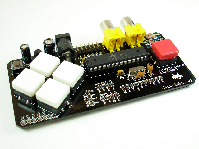
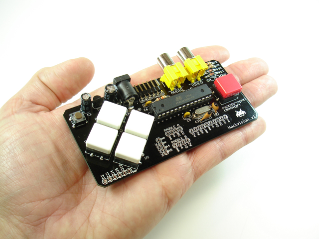
Hackvision is the tiny, hackable, Arduino-based video game system. Available in mid-October with a retail price of under $40 USD.
UPDATE: Hackvision is now available! Learn all the details!
Features:
- NO Arduino is required. Based on Arduino technology so you can write your own games and upload them using the Arduino IDE. All you need is a USB-Serial cable or adapter like this or this.
- Connects directly to your TV with standard RCA connections. One for audio, one for video. Works with NTSC or PAL (Europe, Africa, Asia, South America) TVs.
- Integrated button controller right on the PCB.
- Preloaded with awesome Space Invaders and Pong games. More games coming. You can write them, too.
- Other controllers supported: Wii nunchuk, SuperNES, or paddle controllers you can make from a potentiometer and button.
- Software libraries for game development and controller support.
- High score files stored in EEPROM so they are retained even with power off.
- All unused pins broken out to pads for your hacking pleasure!
- Non-conductive adhesive foam pad protects the bottom of the board from your fingers.
- All through-hole components. Kit can be assembled in 30-60 min. Fully assembled and tested units will also be available.
- Additional accessories will be available for purchase including 9V adapters, RCA cables, Wii nunchuk breakout boards, paddle controller kits, USB-Serial adapters, etc.
Could this be the perfect gift for the 2010 holiday season? (yes)
Here’s a preview of the Space Invaders game. I let the title sequence run before I started playing:
Distributors may email sales@nootropicdesign.com for distributor pricing.
Arduino Breathalyzer: Calibrating the MQ-3 Alcohol Sensor
Difficulty Level = 3 [What’s this?]
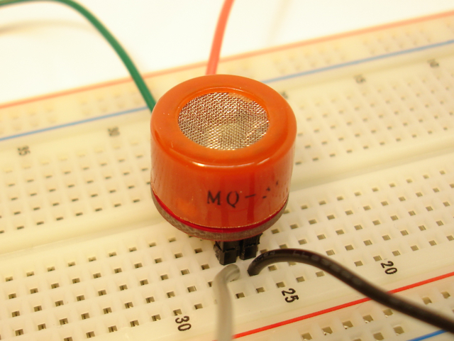
The MQ-3 is an alcohol gas sensor that is available for about $5 from Sparkfun, Seeed Studio, and others. It’s easy to use and has sparked the imagination of anyone who has dreamed of building their own breathalyzer device for measuring the amount of alcohol in the human body. I got an MQ-3 sensor a couple of months ago and have spent a lot of time trying to figure out how to do this. After lots of “data gathering”, I found that this task is not as easy as it sounds.
First of all, don’t try to use the MQ-3 as a way to determine if you are sober enough to drive. If you’ve been drinking, just don’t drive! And if you’ve had a few drinks, don’t do any soldering either.
Toolduino
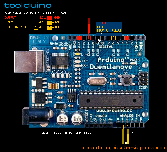
Toolduino is an open-source software tool that you use to test your Arduino circuits. Toolduino communicates with your Arduino through a serial connection so that you can manipulate the pin outputs and read the inputs. Go to the Toolduino page to download it and for all the details on how to use it!
Speed Trap! A GPS-Based Speeding Alert
Difficulty Level = 9 [What’s this?]
This was a fun project I built using a perf-board Arduino with GPS receiver, some LEDs, some long wire, some clever code, and a car!
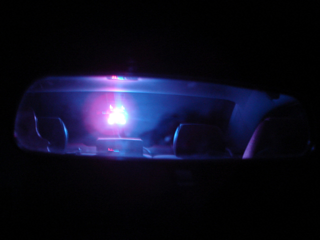
I have this friend that has a speeding problem. So I built this device for my friend so he’ll know when he’s speeding. How will he know? Because when the small perf-board Arduino device with a GPS module detects that his vehicle’s speed is over the speed limit, it turns on a police lights display that is mounted on the inside of his car’s rear windshield. When he sees those flashing police lights in the rear-view mirror, he’ll know he needs to slow down!
OK, it’s me, but you already figured that out. If you weren’t smart, you wouldn’t be here. Here’s a rundown of this project’s features:
- A simple perf-board Arduino circuit with an EM-406a GPS Receiver connected to the microcontroller
- A pair of CAT-5 cables running from the circuit to the back of my Honda Civic
- A small perf-board with red and blue LEDs and two white LEDs representing the headlights of a police car. This small board is mounted on the inside of the rear windshield using suction cups.
- The software running on the microcontroller is programmed to know the speed limit in different locations near where I live and drive. I did this by specifying “speed zones” which are polygons and a speed limit. The polygons are defined as a list of latitude/longitude vertices.
- Whenever the GPS module reports the current position and speed (every second) the code determines which bounding polygon or “speed zone” the car is located in. If the GPS receiver reports that the current speed is greater than the speed zone’s limit, the police lights are activated. If below the speed limit, the lights will be turned off.
The Hardware
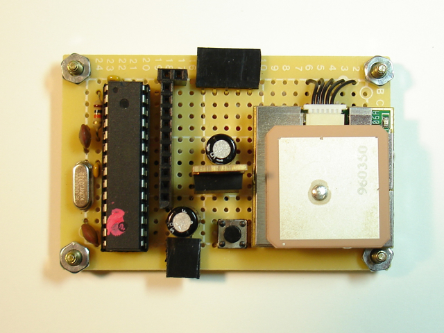
Look at this nice clean circuit…
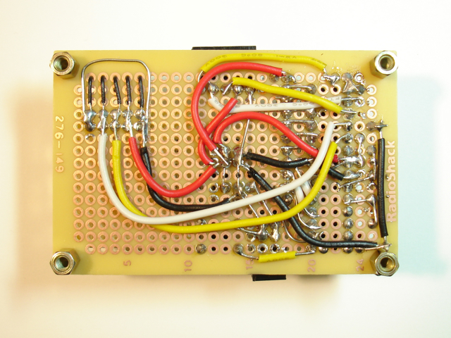
OMG don’t look at the bottom!
Tutorial: Reading a 12-Button Keypad
Difficulty Level = 1 [What’s this?]
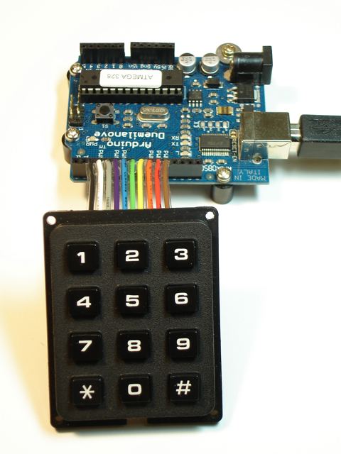
Most keypads like this are wired so it makes it straightforward to figure out what button is being pressed. With 3 columns and 4 rows of buttons, you only need 7 wires. Typically all the buttons in a column are connected together with the same wire, and all the buttons in a row are connected together with the same wire. To determine which button is pressed, you apply a voltage to the wire attached to a column and then check the wires attached to each row to see if current is flowing through any of them. If so, then the switch for a particular button is closed (button pressed). Then you proceed to the next column and try each row again, etc. Not rocket science — just scanning a bunch of switches to see which one is closed. In fact, there is a keypad library in the Arduino Playground that makes it easy to do this.
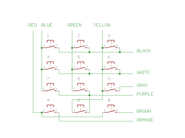
Well, the keypad I bought here has 10 wires instead of 7, and it’s wired in a really goofy way. I’m not sure if this is common, but I thought keypads were generally wired as described above. Here’s the schematic that shows how this one is actually wired:
Regardless, here is Arduino code that I used to scan this keypad. You can do something similar if you have a keypad that is not wired in a straightforward way.
// Pins
#define BLACK 2
#define WHITE 3
#define GRAY 4
#define PURPLE 5
#define BLUE 6
#define GREEN 7
#define YELLOW 8
#define ORANGE 9
#define RED 10
#define BROWN 11

#define STAR 10
#define POUND 11


void setup() {
  Serial.begin(115200);

  // Rows
  pinMode(BLACK, INPUT);
  digitalWrite(BLACK, HIGH);  // set pull-up resistors for all inputs

  pinMode(WHITE, INPUT);
  digitalWrite(WHITE, HIGH);

  pinMode(GRAY, INPUT);
  digitalWrite(GRAY, HIGH);

  pinMode(PURPLE, INPUT);
  digitalWrite(PURPLE, HIGH);

  pinMode(ORANGE, INPUT);
  digitalWrite(ORANGE, HIGH);

  pinMode(BROWN, INPUT);
  digitalWrite(BROWN, HIGH);


  // Columns
  pinMode(BLUE, OUTPUT);
  digitalWrite(BLUE, HIGH);

  pinMode(GREEN, OUTPUT);
  digitalWrite(GREEN, HIGH);

  pinMode(YELLOW, OUTPUT);
  digitalWrite(YELLOW, HIGH);

  pinMode(RED, OUTPUT);
  digitalWrite(RED, HIGH);

}

void loop() {
  int key = scanKeypad();

  if (key != -1) {
    if (key == STAR) {
      Serial.println("*");
    } else {
      if (key == POUND) {
        Serial.println("#");
      } else {
          Serial.println(key);
      }
    }
  }
}

int scanKeypad() {
  int key = -1;

  // Pull the first column low, then check each of the rows to see if a
  // button is pressed.
  digitalWrite(BLUE, LOW);
  if (digitalRead(BLACK) == LOW) {
    key = 1;
  }
  if (digitalRead(WHITE) == LOW) {
    key = 4;
  }
  if (digitalRead(PURPLE) == LOW) {
    key = 7;
  }
  digitalWrite(BLUE, HIGH);

  // Moving on to the second column....
  digitalWrite(GREEN, LOW);
  if (digitalRead(BLACK) == LOW) {
    key = 2;
  }
  if (digitalRead(WHITE) == LOW) {
    key = 5;
  }
  if (digitalRead(PURPLE) == LOW) {
    key = 8;
  }
  digitalWrite(GREEN, HIGH);

  // Third "column".  Note that the 0 key is wired to this column even though
  // the 0 is really in the second column.
  digitalWrite(YELLOW, LOW);
  if (digitalRead(BLACK) == LOW) {
    key = 3;
  }
  if (digitalRead(WHITE) == LOW) {
    key = 6;
  }
  if (digitalRead(GRAY) == LOW) {
    key = 9;
  }
  if (digitalRead(PURPLE) == LOW) {
    key = 0;
  }
  digitalWrite(YELLOW, HIGH);

  // Last "column" is not really it's own column.  Only wired to * and #
  digitalWrite(RED, LOW);
  if (digitalRead(ORANGE) == LOW) {
    key = STAR;
  }
  if (digitalRead(BROWN) == LOW) {
    key = POUND;
  }
  digitalWrite(RED, HIGH);

  return key;
}
