Forum Replies Created
-
AuthorPosts
-
Michael
KeymasterFirst get the voice changer project working without using a microphone. Use the output of a computer and turn the volume up so the signal is strong. Have you tried this?
As for microphones, they are usually *powered* by the amplifier they plug into. The Audio Hacker does not provide power to a microphone and the input was not designed to be for a microphone. It is possible to connect a microphone if you also provide power for it. See this project: https://nootropicdesign.com/projectlab/2013/07/05/electret-microphone-audio-hacker/
Sorry if this is disappointing, but everyone seems to be trying to use this in costumes with 3rd party microphones and it’s not designed for that.
KeymasterHi Andy,
With all your experience in this area, I’m sure you know much more than me. Using the closed captioning project as a guide, you might be able to pluck out the bits from line 16. It will take trial and error. Hopefully, an Arduino microcontroller is fast enough for the 2us wide bits. If not, it’s possible to wire the Video Experimenter to other microcontrollers like in this project: https://nootropicdesign.com/projectlab/2011/07/13/ve-on-the-seeeduino-mega/
Have fun!
KeymasterMike, thanks for reporting that issue. I didn’t know that Arduino would try to update the library from the older version that the Video Experimenter version is based upon. The Video Experimenter and its library were developed in 2010, long before the library management features in Arduino. Thanks again for posting.
-Mike
KeymasterNext to the start button are two solder pads that you can wire to any sort of switch. So if you have a motion sensor that can activate a relay or switch, that would work.
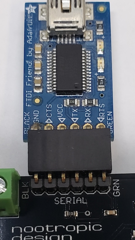
KeymasterI am glad it works for you now. I totally understand how “GRN” could mean “ground”. There just happens to be a long-standing tradition of labeling USB-Serial adapters with “green” and “black” designations. Makes sense in English, but not everyone is speaking English, of course.
Again, sorry about the problems and about the slow responses.
-Mike
KeymasterI am sorry for the slow response, my apologies.
How are you connecting the FTDI programmer to the board? There must be some kind of problem with the connection. Can you show me a picture of how you are connecting it?
It should be connected like this:
https://nootropicdesign.com/store/wp-content/uploads/2024/02/ftdi_connection.jpg
Also, the logic level is 5V on this board. Maybe you are using 3.3V logic level programmers?
KeymasterHi,
What errors are you getting? There are no further instructions on the site because the Game Time Pro is simply an Arduino UNO with a normal ATmega328 microcontroller. If you can see the serial port and compile the code, it should upload just like any other Arduino.
I assume you got the code from the GitHub repo: https://github.com/nootropicdesign/game-timer-pro
What errors do you get when uploading?
-Mike
KeymasterIt’s not possible to configure it for two defuse methods, but this can be accomplished with custom programming. I have implemented similar things for other customers. We offer this service for a small fee. See this:
KeymasterI LOVE IT. Thanks for posting this, and great job with the development. I wrote Asteroids about 12 years ago when I was first learning microcontroller development, and I am still really happy with how it turned out. I love the round LCD, and am impressed that the wrapping on the edges worked so well. Nice work.
-Mike
KeymasterHi Tia, sorry for the slow response.
The source code is available on GitHub here: https://github.com/nootropicdesign/defusable-clock
It is possible to change the functionality and add features, but the kit is a much older product than the newer Game Timer Pro with all the features. It’s not easy to program embedded software, so I wish you luck, but I wouldn’t be able to help you. The reason I produced the Game Timer Pro is to incorproate all the features that so many people wanted.
I’m not sure what vias you are referring to. All features of the board are described on the product manual page: https://nootropicdesign.com/defusable-clock/
Have fun!
-MikeKeymasterHmm. To be honest, there’s essentially nothing on the Digit Shield that can fail. It’s so simple. If the two right digits are working then that means both chips are working. The only distinction between left and right displays is the transistors. The two left-most transistors on the board are associated with the left display. Maybe double check the connections there.
Or load a different program on the Arduino that just displays numbers on the left and see if it works?
Mike
KeymasterThe input is not connected to an Arduino pin input directly. There are breakout pads right behind the input jack so that you can connect wires directly to the input circuit.
KeymasterNo, I’m afraid not.
KeymasterYes, these are changes you can make to the sampler programs. It requires coding, though, and it depends on how comfortable you are with Arduino coding.
KeymasterJohn,
No, I’m afraid there is not a simple way. You would have to wire all 12 display connections to another display. I’m not sure how well that would work, as the power would be split between both displays and they would become dimmer.
-
AuthorPosts