
Arduino shield for realtime audio processing
Preparation
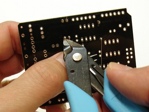
- Gather required tools: soldering iron, solder, wire cutters, and some tape for holding components in place while you solder them. I recommend wearing eye protection when you are clipping off the excess leads on components because the small pieces of metal can go flying in any direction.
- Check the parts list to make sure you have everything:
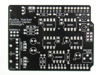
PCB
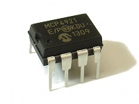
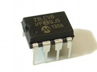
MCP4921 DAC IC
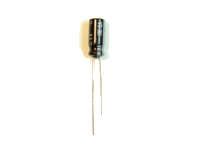
10uF capacitor (2)
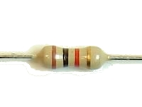
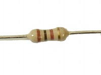
1K ohm resistor
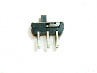
DPDT slide switch
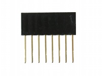
8-pin female header (2)
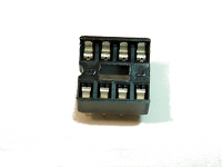
8-pin IC socket (5)
23LCV1024 SRAM IC (2)
1uF capacitor
100K ohm resistor (2)
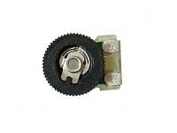
100K ohm PCB mount pot
6-pin female header (2)
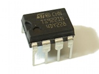
TS922IN or TLV2462 opamp IC
.1uF capacitor (4)
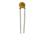
47nF ceramic disc capacitor
470 ohm resistor (2)
10K audio pot
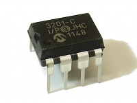
MCP3201 ADC IC
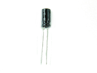
100uF capacitor
100 ohm resistor (2)
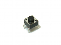
tactile switch (2)
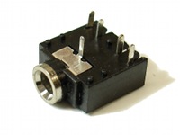
3.5mm audio jack (2)
Step 1
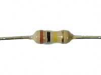
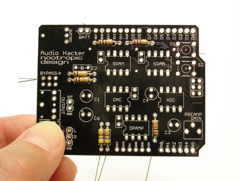
First we will start by soldering the 7 resistors. Resistors do not have polarity, so orientation does not matter.
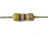
Insert the resistors into the board in the appropriate places. R1 and R2 are 470 ohm resistors with color code yellow-purple-brown-gold.
R3 and R4 are 100K with color code brown-black-yellow-gold
R5 is 1K with color code brown-black-red-gold
R6 and R7 are 100 ohm with color code brown-black-brown-gold
Step 2
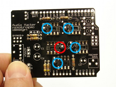
Place the five IC sockets into the board. Pay close attention to the location of the notch in the socket, as this will help you insert your chips with the correct orientation. All of the sockets have their notch on the left side, EXCEPT the DAC chip, which has the notch on the right side. This is circled in red.
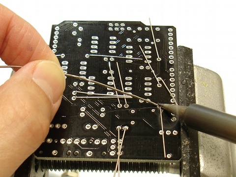
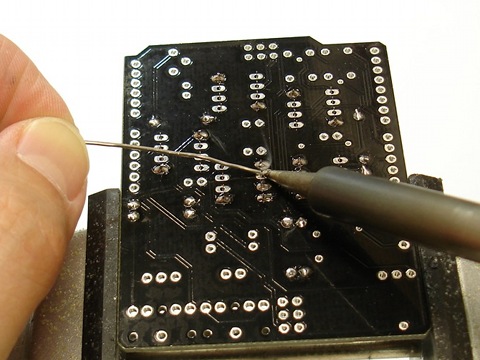
You may wish to hold the sockets in place with some tape while you solder them. Turn the board over and solder the sockets into place.
Step 3
Insert the four .1uF capacitors into the board. They are all near IC chips and the silkscreen outline is a small rectangle. These caps are not polarized, so orientation does not matter.
Turn the board over and solder the capacitors into place.
As before, clip off the excess leads.
Step 4
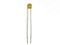
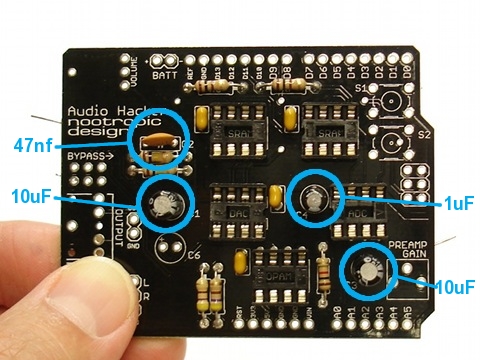
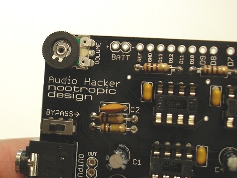
Now insert the 47nF ceramic disc capacitor (marked “473”) just above the 100K resistors. It is labeled C2 on the board. This cap is not polarized, so orientation does not matter.
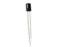
Insert the two 10uF capacitors in positions labeled C1 and C3. These capacitors ARE polarized, so ensure that the long lead of the capacitor is in the hole marked with a ‘+’ symbol. This is the left pad of each of these caps.
Next insert the tiny 1uF capacitor in position labeled C4 near the ADC IC socket. This capacitor is polarized, so ensure that the long lead of the capacitor is in the hole marked with a ‘+’ symbol.
Turn the board over and solder the capacitors into place.
Clip off excess leads.
Step 5
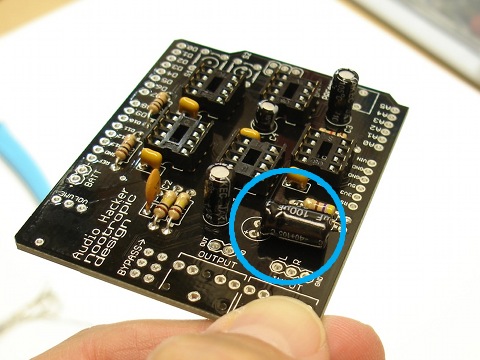
Insert the large 100uF capacitor into the position marked C6. This cap is polarized, so ensure that the long lead is in the pad marked with a ‘+’ symbol.
This cap is taller than the others, so if you plan on using a DJ Shield on top of the Audio Hacker, then I recommend laying this capacitor down on its side as shown in the picture. Otherwise the cap is too tall to use the DJ Shield.
Turn the board over and solder the capacitor into place.
Clip off excess leads.
Step 6
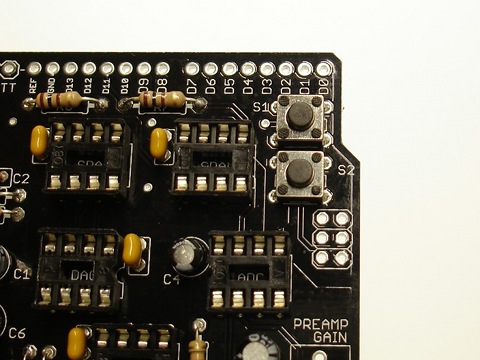
Insert the two small buttons into the board near the upper left. They are labeled S1 and S2.
Turn the board over and solder the contacts for the buttons.
Step 7
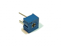
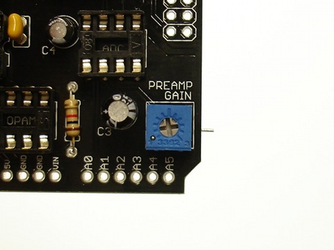
Insert and solder the small 100K potentiometer in the position marked “PREAMP GAIN”. It’s a good idea to turn this pot counterclockwise to its lowest position now.
Clip the excess leads.
Step 8
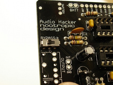
Bypass switch: Insert the small slide switch into the 6 pads near the label “BYPASS”.
Turn the board over and solder the six connections.
Step 9
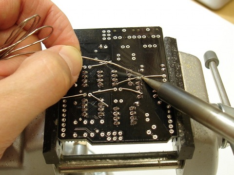
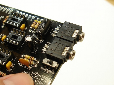
Audio jacks: Insert the two audio jacks into the board so that they lay flat on the board.
Turn the board over and solder the five connections for each jack.
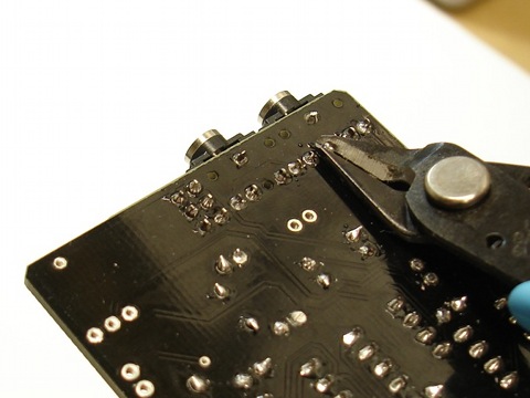
In order for the Audio Hacker shield to sit nicely on your Arduino, you may want to clip the leads on the input jack. This jack will be directly above the Arduino power connector and the leads may touch the connector.
Step 10
Volume knob: insert the knob in the upper left corner of the board. You may want to hold it in place with some tape.
Turn the board over and solder the connections.
Step 11
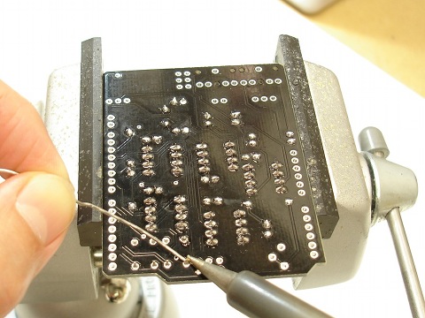
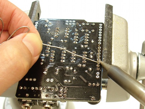
Headers: Now it’s time to solder the headers in place. There are two 8-pin headers and two 6-pin headers. It can be tricky to get them to stand straight on the board while you solder, so try using some tape.
Turn the board over and solder all the header connections. Make sure your headers are straight so that your shield fits nicely into your Arduino board.
Step 12
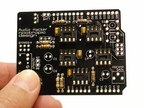
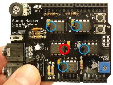
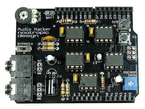
Insert the five chips into the sockets. Pay close attention to which chip goes into which socket! Click the image on the left to see an enlarged view.
The two SRAM chips marked “23LCVB” are near the top of the board. The notch in the ICs is on the left.
The MCP4921 DAC chip is in the center of the board. The notch in the ICs is on the right. This is circled in red.
The MCP3201 ADC chip is near the right side of the board. The notch in the IC is on the left.
The TS922IN or TLV2462 opamp chip is near the bottom of the board. The notch in the IC is on the left.
Before you use the board, double check that you have each chip in the correct place, and that the chips are oriented correctly!
Step 13 (for Mega and Leonardo)
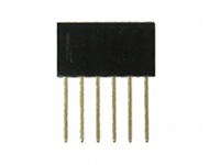
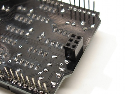
If you plan to use the Audio Hacker on an Arduino Mega or Leonardo, you MUST solder a 6-pin female header onto the bottom of the board on the right side.
Position the header as shown and solder the connections on the TOP of the board.
Step 14
Bask in the glory of your success and have a beer. If you don’t drink or are too young to drink, have a piece of candy or something.
Your next step is to test the Audio Hacker with a simple sampling project. Set the preamp gain to the lowest level and the bypass switch to the left position. Download the Audio Hacker library and load the 12-bit sampler as described in this project. Read the usage guide so you understand the input and output settings for your board.
Troubleshooting
If you’ve assembled the Audio Hacker shield and it doesn’t seem to work, let’s ask ourselves some questions:
- Does the audio sound distorted? Make sure you set the preamp gain to the lowest position (counterclockwise) if you are feeding in an audio source like an MP3 player or computer.
- Does the audio have a lot of static and noise, or is it flakey when you touch the Arduino? Make sure that the Audio Hacker shield is properly inserted into the Arduino. If some of the shield pins are not seated firmly into the Arduino headers, the board will not function properly. This malfunction is characterized by loud static and noise when simply playing audio through the shield.
- Are you sure it’s not working the way it’s supposed to? Consult the usage guide.
- Are you sure you’ve soldered everything together correctly? Double check your soldering connections. If any look suspect, reheat them with a soldering iron. Also remember that many bad connections look fine.
- Did you install the chips in the right positions? There are 4 different kinds of chips and they are not interchangeable!
- Did you orient the chips correcly? Pay close attention to which side the notch on the end of the chip is facing.
- Are you using an Arduino Mega or Leonardo? These Arduino boards require a 6-pin female ICSP header to be soldered onto the bottom right side of the board.
- Use a multimeter to help you determine if everything is connected. You can refer to the schematic available on the design page.
- If you are still having problems, email support@nootropicdesign.com and be sure to include exact details about how the device behaves. Send pictures, if you can. High-resolution, clear photographs, not blury mobile phone pictures.