The RGB Matrix Backpack is a small board that connects to the back of an RGB LED matrix panel. Compatible panels include:
Adafruit 16×32 matrix panel
Adafruit 32×32 matrix panel (6mm pitch)
Tinkersphere TS1175 16×32 matrix panel
Tinkersphere TS-867 32×32 matrix panel
It is a very convenient way to control these awesome panels. The new “v2” version of this board works on both 16×32 and 32×32 panels! The board is simply a small Arduino. You can easily program the board using the Arduino IDE. As you can see from the video below, it’s possible to create great color animations, completely in Arduino programming!
To program the board, you’ll need a USB-Serial adapter or cable to connect to the board’s 6-pin serial connector (more info below). Or you can program the ATMega328 chip using your Arduino board and move the chip to the RGB Matrix Backpack for testing.
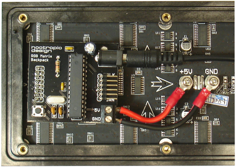
The board snaps onto the back of the panel and provides power to the panel through the terminal block connections. The board should be powered by a 5V regulated power adapter that can deliver up to 2A. Adafruit and Tinkersphere sell the appropriate power adapters: Adafruit 276, Tinkersphere TS1114.
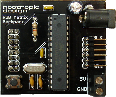
Board Features
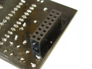
The 8×2 female header on the back of the board allows this backpack board to simply snap onto the back of the matrix panel.
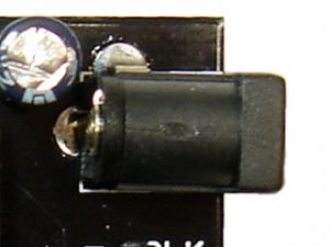
2.1mm power jack for a regulated 5V power supply. The 5V supply should be able to deliver 2A of current to meet the demands of the matrix panel. We strongly recommend our 2A power supply, or this power supply provided by Adafruit or this power supply provided by Tinkersphere for use with the matrix panel.
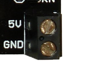
The terminal block is used to provide power to the RGB matrix panel.
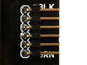
The 6-pin programming header makes it easy to program the board using the Arduino IDE and a cable or adapter like the Adafruit FTDI Friend, Adafruit’s FTDI cable and Tinkersphere’s TS-135 FTDI cable.
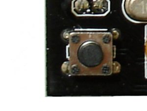
A small tactile button can be used as an input to your Arduino program. It is connected to Arduino pin 11. Note that if you have the older version board (it does not say “v2”), this button is connected to Arduino pin 10.
Programming the Matrix Backpack
To program the backpack board, you use it just like an Arduino. The board type to select in the Arduino IDE is “Aruino Uno”. You need to connect an FTDI cable or adapter like the FTDI Friend, Adafruit’s FTDI cable, Tinkersphere’s TS-135 FTDI cable.
Adafruit provides useful Arduino libraries for controlling the RGB Matrix Panel. You can download the libraries and learn how to use them on their matrix tutorial page. You don’t have to worry about any of the complex wiring — just skip down to the sections “Test example code” and “Library”.
The ATmega328 chip in the backpack kit comes preloaded with a demo, depending on whether you specify that you have a 16×32 or 32×32 panel when you order. If you specify 16×32, then it comes with the animation shown in the video above. If you specify that you have a 32×32 panel, it comes loaded with the “plasma_32x32” sketch included in the Adafruit RGBmatrixPanel library.
To change the demo program for the 16×32 panel, download the sketch here. Make sure you’ve installed the Adafruit libraries correctly. Compile the sketch and upload it to your board. The board type to select in the Arduino IDE is “Aruino Uno”. If you have an old version of this board (it does not say “v2”), then change the definition of LAT to A3:
#define LAT A3
Only version v2 of this board may be used with 32×32 panels. The 32×32 example sketches in the Adafruit RGBmatrixPanel can be used without modification. To use a 16×32 example sketch from the Adafruit RGBmatrixPanel library, you must change the definition of the latch pin from A3 to 10. Change
#define LAT A3
to:
#define LAT 10