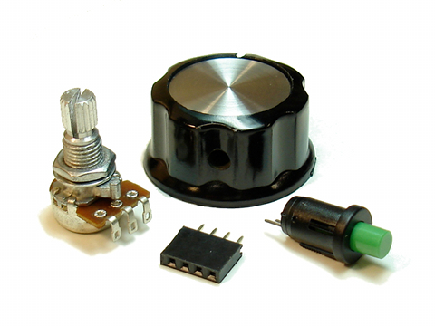
The paddle mini-kit is available in the nootropic design store and includes a 10K ohm potentiometer, a pushbutton, a knob, and a 4 pin female header. You can easily build paddle controllers to use with your Hackvision. This page shows an example of how to build a paddle controller.
For this controller I used a small project box from All Electronics. The mini-kit does not come with wires, so it is assumed you’ve got some solid wire to use.
Step 1
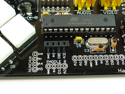
Insert the 4-pin female header into the holes in the PCB marked “PADDLE A” or “PADDLE B”. In this picture, I inserted the header in the PADDLE A position. Use some tape to hold the header in place so that it is vertical and stable.
Step 2
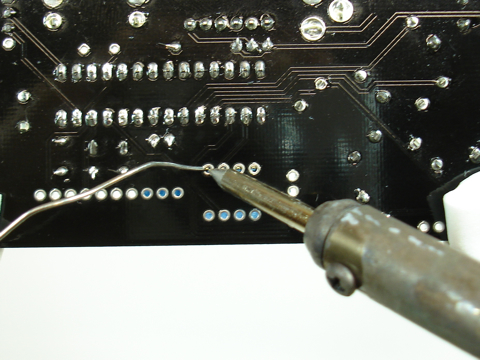
Turn the board over and solder the 4 joints. Make sure that the header stays as vertical as possible.
Step 3
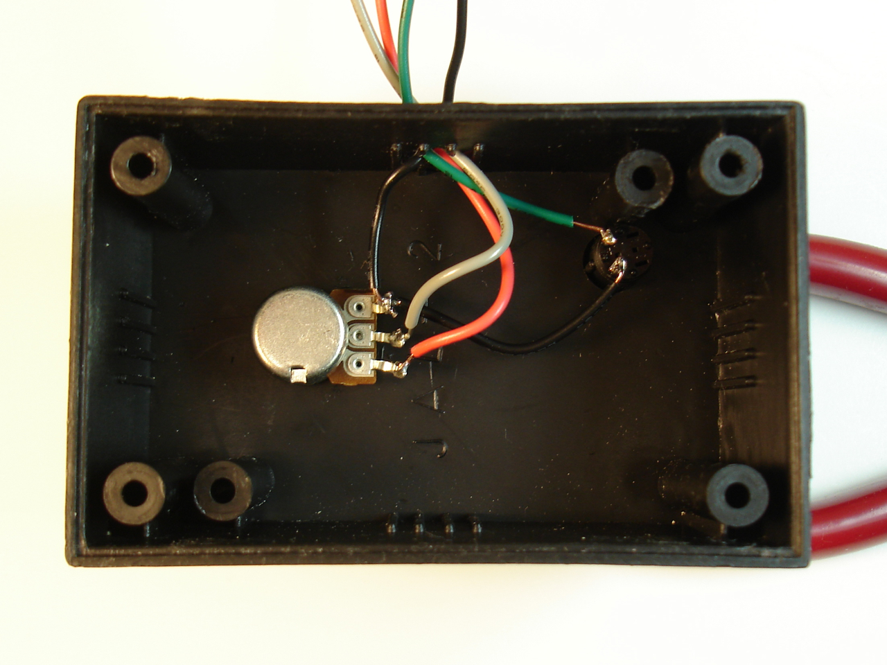
Solder wires to your button and potentiometer. The potentiometer has a connection to ground (black wire), 5V (red wire), and a connection for the analog voltage output (gray wire). The middle contact of the potentiometer is called the “wiper” and it is connected to the gray wire which will be used to read the position of the pot. Note which contacts that the ground and 5V wires are connected to — use the same connections as seen in this bottom view. The button has two contact: one for the digital input (green), and one for ground. In this picture, I connected the ground wire to the ground connection on the potentiometer.
Click image for a larger view.
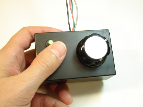
Here is the controller from the top.
Step 4
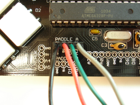
Connect the paddle wires to the header on the PCB. The wire for the button (green in my pictures) goes in the digital input pin marked D0 for PADDLE A, and D1 for PADDLE B. The analog input (gray in my picture) goes in the analog pin marked A3 for PADDLE A and A2 for PADDLE B.
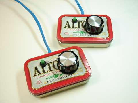
Here are some stylish paddles I built using Altoids tins. I put shrink-wrap tubing around the four wires to keep it nice and neat.
