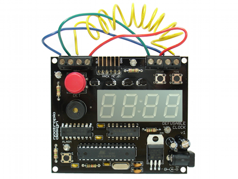
Build a clock that looks seriously dangerous! Perfect for Airsoft and Escape Rooms.
Preparation
- Gather required tools: soldering iron, solder, wire cutters, and some tape for holding components in place while you solder them. I recommend wearing eye protection when you are clipping off the excess leads on components because the small pieces of metal can go flying in any direction.
- Check the parts list to make sure you have everything:
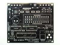
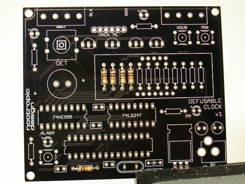
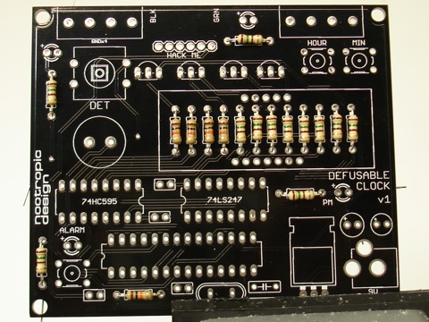
PCB
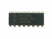
74HC595 IC
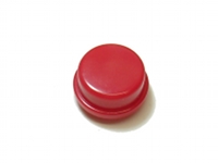
red round button cap
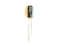
10uF capacitor
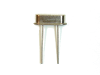
16MHz crystal
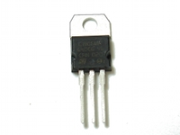
L7805 voltage regulator
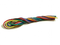
wires (8)
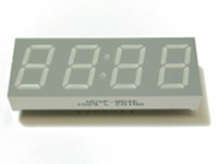
clock display
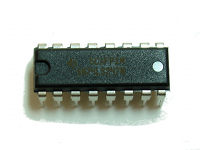
74LS247 IC
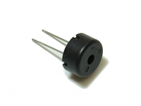
piezo buzzer
22pF capacitor (2)
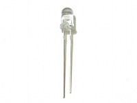
red LED (4)
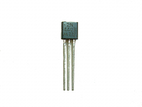
2N4403 PNP transistor (4)
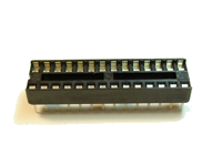
28-pin IC socket
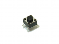
tactile switch (3)
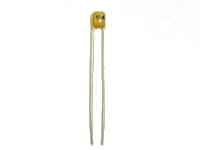
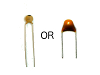
.1uF capacitor (4)
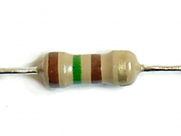
150 ohm resistor (12)
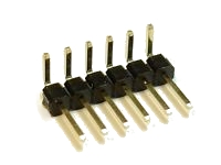
6-pin right angle male header
terminal block (4)
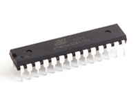
ATmega328 microcontroller IC
12mm tactile switch
100uF capacitor
10K ohm resistor (5)
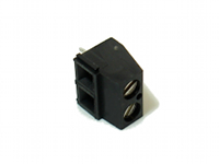
2.1mm barrel power jack
1N4001 diode
Step 1
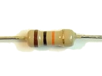
Insert the 10K resistors into place. There are 5 10K resistors and they are coded brown-black-orange-gold. Resistors do not have polarity, so orientation does not matter.
Four of the resistors go near the center of the board and will be under the LED display. They are labeled “10K”. The fifth 10K resistor is at the bottom of the board and is also labeled “10K”.
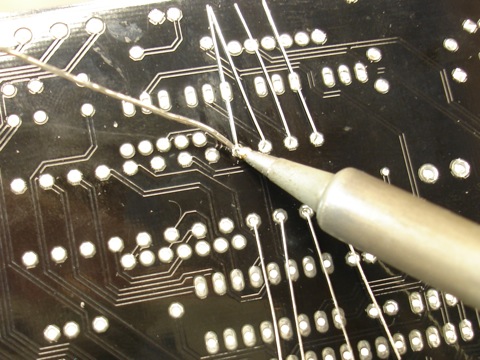
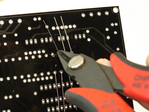
Using wire cutters, clip off the excess leads near the solder joint.
Step 2
Insert the twelve 150 ohm resistors into place. They are coded brown-green-brown-gold. Eight of them will be under the LED display, and the other four will be near the LEDs in various locations on the board.
Turn the board over and solder the resistors into place.
As before, clip off the excess leads.
Step 3
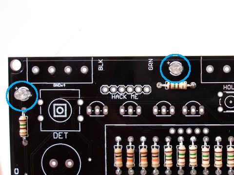
Solder the four LEDs into place. They are near the 150 ohm resistors and one of the pads is marked with a ‘+’ sign. LEDs are polarized and the longerlead on the LED goes in the pad marked ‘+’. Ensure that the longer of the two leads on each LED is inserted into the hole marked ‘+’.
Turn the board over and solder the LEDs into place.
As before, clip off the excess leads.
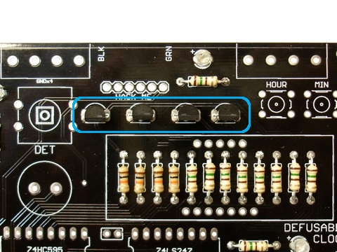
Step 4
Insert and solder the four transistors that are just above the place for the LED display. Be sure to position the transistor according to the shape on the PCB silkscreen (flat side facing downward).
Turn the board over and solder the 3 pins on each transistor.
Clip off excess leads.
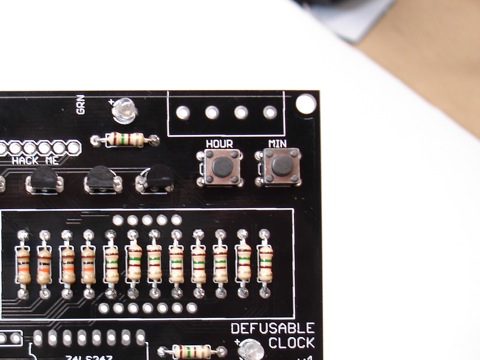
Step 5
Insert the three small button labeled “HOUR”, “MIN”, and “ALARM”. They should snap into place nicely.
Turn the board over and solder the four contacts of each button.
Step 6
Insert the 28 pin IC socket, ensuring that the notch at the end of the socket is aligned with the notch on the PCB silkscreen. The notch should be pointing to the left side of the board. You may want to use a piece of tape to hold the socket into place flat against the board.
Turn the board over and solder all 28 contacts of the socket, ensuring that the socket stays flat against the board.
Step 7
Insert and solder the four .1uF capacitors. These very small capacitors are yellow and may be labeled “104”. These are not polarized, so they can be oriented either way.
Turn the board over and solder them into place.
Clip the excess leads.

Step 8
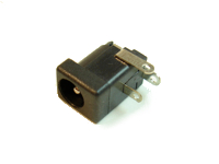
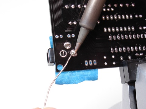
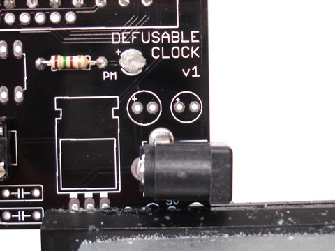
Power jack: position the DC power jack in the 3 large holes in the lower left hand of the board. Use some tape to hold the jack into place in the 3 holes and turn the board over.
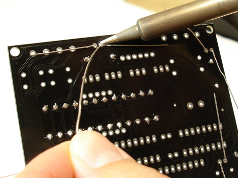
Apply generous heat to the lead and annular ring (the ring around the hole) at the same time, and push a generous amount of solder into the hole. Keep going until the hole is filled. Be patient, you can do it! This uses a lot of solder.
Step 9
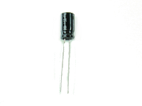
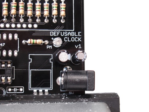
Capacitors: The 100uF and 10uF capacitor are just above the power jack. The 100uF capacitor is slightly larger than the 10uF capacitor, and goes in on the left. These capacitors are polarized, so the longer lead goes in the hole marked ‘+’.
Turn the board over and solder the capacitors into place.
Clip the excess leads.
Step 10
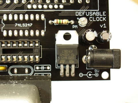
Insert the voltage regulator into the 3 holes near the power jack. Bend the voltage regulator down so that it lays flat against the board and matches the part outline on the board.
It is not important to get the regulator to lay perfectly flat on the board.
Turn the board over and solder the 3 connections.
Clip the excess leads.
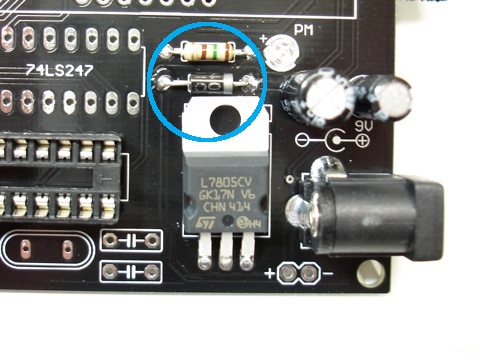
Step 11
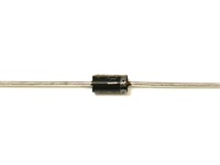
Insert the protection diode into place just above the voltage regulator. IMPORTANT: make sure the white stripe on the diode is to the right, just as shown on the silkscreen.
Turn the board over and solder the 2 connections.
Clip the excess leads.
Step 12
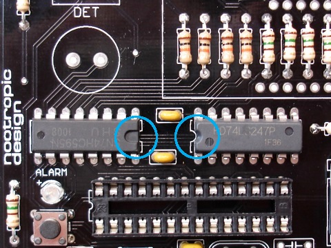
Integrated circuits: Insert the 74HC595 chip and the 74LS247 chip into the board.
IMPORTANT: these chips are not the same! You must put the correct chip in the correct spot. Pay close attention to the part numbers.
IMPORTANT: make sure the small notch on one end of each chip is aligned with the notch on the chip outline printed on the board. The notches face each other. The print on the 74HC595 chip on the left will be upside down.
Turn the board over and solder every connection on the chips. You may need to use some tape to hold the chips flat against the board.
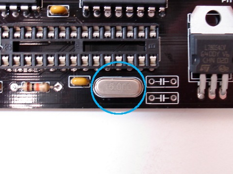
Step 13
Insert the 16MHz crystal in to place just under the IC socket. Crystals do not have polarity, so orientation does not matter.
Turn the board over and solder.
As always, clip off the excess leads.
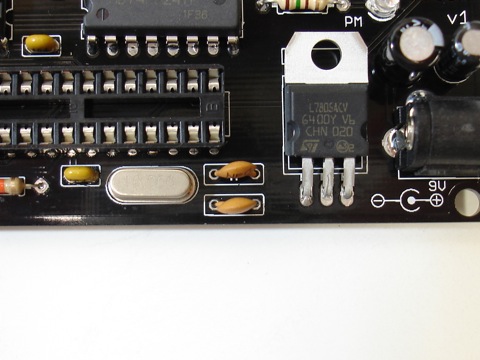
Step 14
Position the two 22pF capacitors near the crystal. These capacitors are not polarized so their orientation does not matter.
Turn the board over and solder.
Clip off the excess leads.
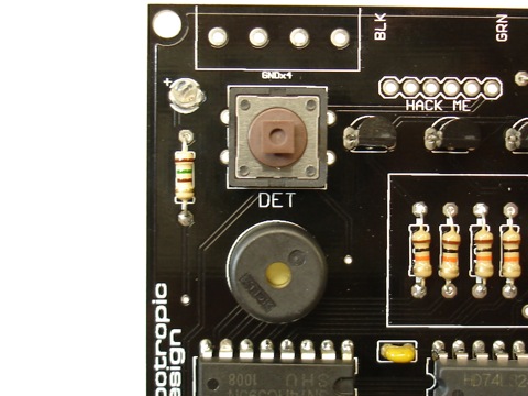
Step 15
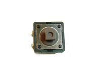
Insert and solder the large 12mm button and the piezo buzzer. The buzzer does not have polarity and can be inserted either way.
Clip the excess leads from the piezo buzzer.
Step 16
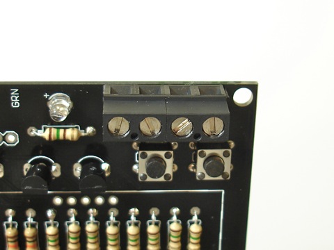
Terminal blocks: There are four two-position terminal blocks with screw connections. They are designed to be connected together. Each piece has a slot on one side and a raised edge on the other. Two pieces can be connected by sliding the raised edge into the slot of the other block. Connect two pairs of blocks together so that you have two four-position blocks.
Position the blocks on the board near the top in the rectangular outlines with four holes. Ensure that the terminal entry holes are facing upward so wires can be inserted.
Turn the board over and solder the four connections on each block. You may want to use some tape to hold the blocks in place.
Step 17
(This step is optional if you don’t ever plan on programming your clock using Arduino.)
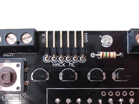
Position the 6-pin right angle header on the board as shown. You may use some tape to hold it in position.
Turn the board over and solder the 6 connections.
Step 18
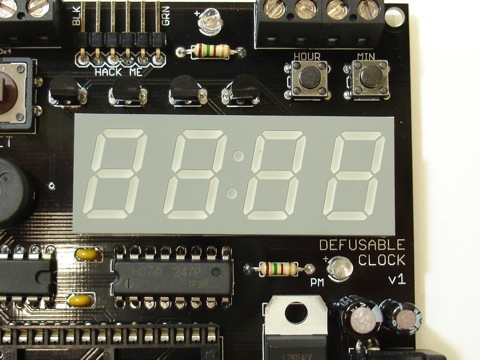
Now it’s time to solder the LED display into place. The display may not touch the board because of the resistors, but the display should lie flat on the resistors. Use some tape to hold the display in place.
Turn the board over and solder the 12 connections, ensuring that the display is flat on the resistors.
Step 19
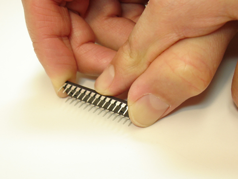
The pins ATmega chip are bent slightly outward and the chip won’t fit nicely into the socket. Carefully bend the pins of the ATmega328 chip inward by holding the chip against a flat surface and applying a little pressure. Repeat for the other row of pins.
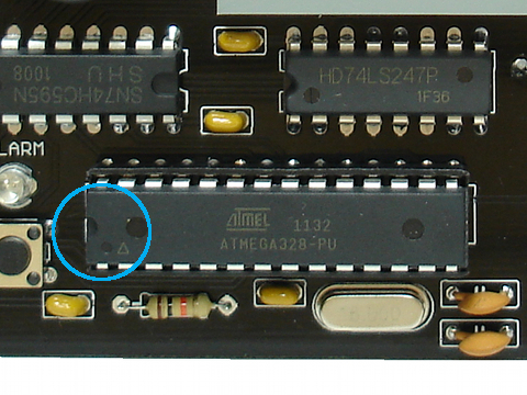
Insert the chip into the socket with the notch at the end of the chip aligned with the notch on the silkscreen (on the left end).
Push the chip firmly into the socket.
Step 20
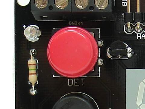
Snap the red button cap onto the large button.
Step 21
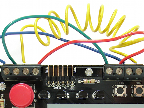
Strip the insulation off of four pieces of wire.
Connect four wires from the four terminals on the left to the four terminals on the right. The ordering of the wire connections does not matter. That is, each wire from the left can connect to any terminal on the right. (Because all the connections on the left are connected to ground.)
Step 22
Bask in the glory of your success and have a beer. If you don’t drink or are too young to drink, have a piece of candy or something.
Your next step is to connect a 9V DC power source with a 2.1mm center positive plug and then read the usage guide.
We hope you build a great-looking clock and send pictures for the gallery.
Now have fun and don’t get into trouble!
Troubleshooting
If you’ve assembled the Defusable Clock and it doesn’t seem to work, let’s ask ourselves some questions:
- Are you sure it’s not working the way it’s supposed to? Consult the usage guide.
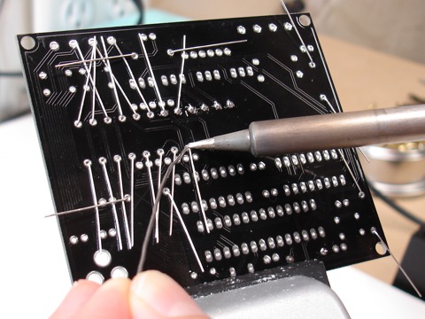
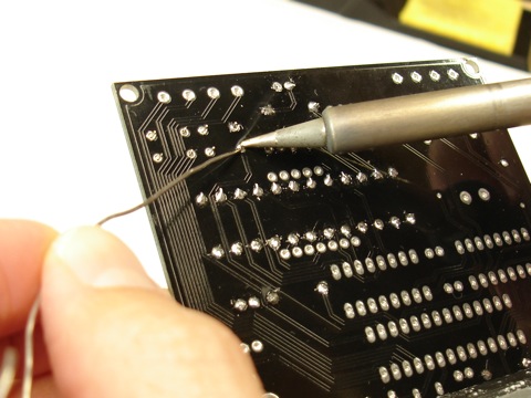
- Are you sure you’ve soldered everything together correctly? Look at this picture of good soldering. Note how none of the solder connections are shorted together. Your soldering should look similar. Double check your soldering connections. If any look suspect, reheat them with a soldering iron. Also remember that many bad connections look fine.
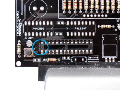
- Did you install the 74HC595 and 74LS247 chips in the right position? The 74HC595 is on the left and the 74LS247 is on the right.
- Did you orient the 74HC595 chip correctly? The notch points to the right, which means that the print on the chip is upside-down.
- Did you orient the ATmega328 chip correcly? The notch is on the left.
- Is the voltage regulator getting hot? If so, disconnect power immediately and use a multimeter to determine if VCC is shorted to ground. Test continuity between the rightmost two pins on the voltage regulator (as viewed from the front of the board). If there is no resistance between these pins, you have a short.
- Use a multimeter to help you determine if everything is connected. You can refer to the schematic available on the design page.
- If you are still having problems, email support@nootropicdesign.com and be sure to include exact details about how the clock behaves. Send pictures, if you can. High-resolution, clear photographs, not blury mobile phone pictures.