
Preparation
- Gather required tools: soldering iron, solder, wire cutters, and some tape for holding components in place while you solder them. I recommend wearing eye protection when you are clipping off the excess leads on components because the small pieces of metal can go flying in any direction.
- Check the parts list to make sure you have everything:
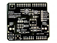
PCB
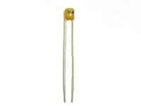
.1uF capacitor (3)
75 ohm resistor
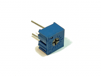
100K PCB mount pot
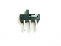
DPDT slide switch
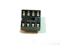
8-pin IC socket
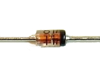
1N4148 diode (2)
20K ohm resistor
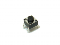
tactile switch
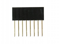
8-pin female header (2)
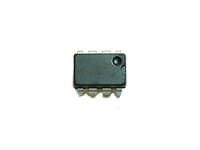
LM1881 IC
330 ohm resistor
680K ohm resistor
3-pin male header
6-pin female header (2)
RCA jack (2)
1K ohm resistor
10K PCB mount pot
jumper
Step 1
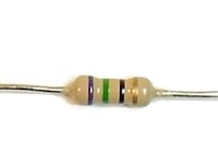
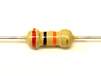
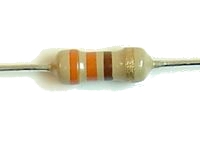
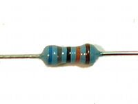
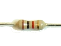
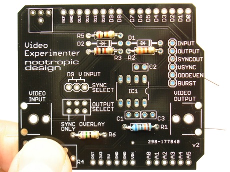
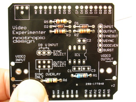
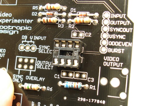
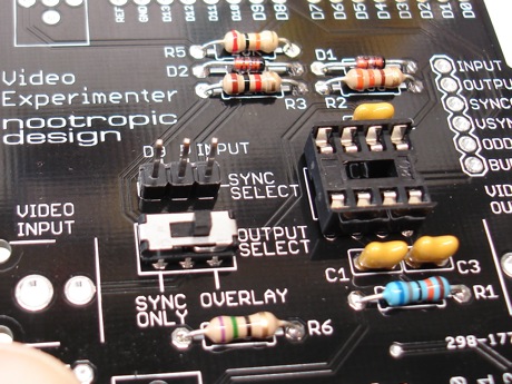
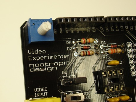
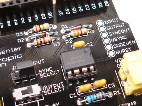
Insert resistors R1, R2, R3, R5, and R6 into place. R1 is 680K and is coded blue-gray-black-orange-brown.
R2 is 330 ohms and is coded orange-orange-brown-gold.
R3 is 1K ohms and is coded brown-black-red-gold.
R5 is 20K ohms and is coded red-black-orange-gold.
R6 is 75 ohms and is coded purple-green-black-gold.
Resistors are not polarized so you don’t have to worry about how they are oriented.
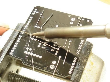
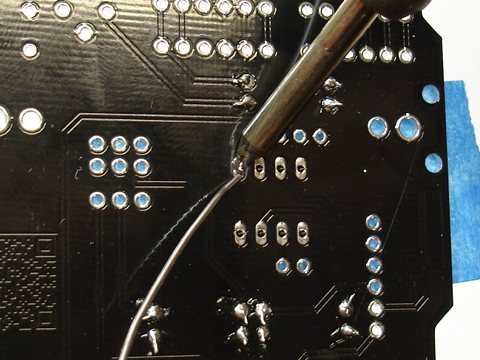
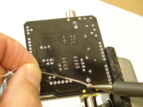
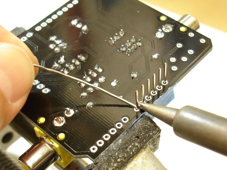
On the back of the board, solder the resistors by heating both the pad and the lead for a couple of seconds, then applying solder.
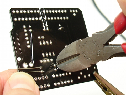
Using wire cutters, clip off the excess leads near the solder joint.
Step 2
Insert the two diodes D1 and D2 into position. Both diodes are the same. Diodes are polarized and must be oriented correctly. The black band around the end of the diode goes on the right side.
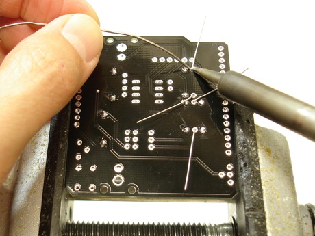
Solder the diodes into place.
Clip off the excess leads.
Step 3
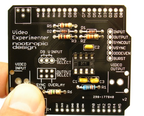
Solder the IC socket into place. Position the socket so the notch in one end of the socket is aligned with the notch drawn on the silkscreen. Use some tape to hold the socket flat against the board while you solder it into place. There are 8 pins to solder. Make sure you heat the pin and the pad for a couple of seconds before applying the solder.
Step 4
Insert and solder the three tiny .1uF (or 100nF) capacitors C1, C2, and C3 into place. They are all near the IC socket.
Turn the board over and solder.
Clip off excess leads.
Step 5
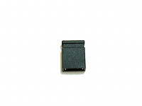
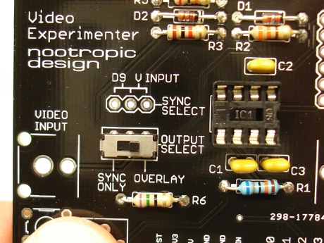
Insert and solder the OUTPUT SELECT switch into place. Orientation of the switch does not matter. You might want to use some tape to hold it flat against the board.
Turn the board over and solder.
Step 6
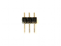
Insert and solder the SYNC SELECT 3-pin male header near the switch. Insert the header into the board with the long end of the pins pointing upward and short end of the pins inserted into the board. Use some tape to hold the header straight.
Turn the board over and solder.
Place the jumper onto the two rightmost pins of the header to select the sync signal from V INPUT.
Step 7
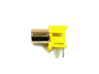
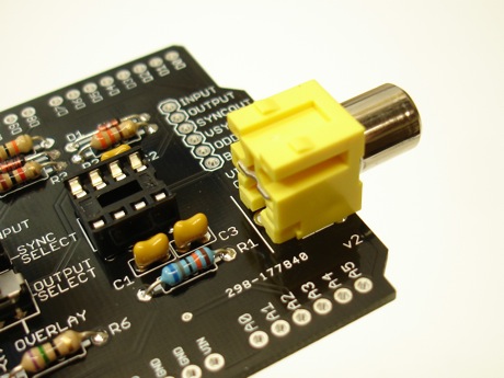
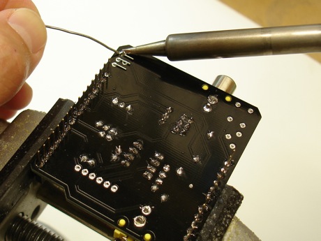
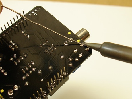
RCA jacks: position one of the jacks in place on the board. If the plastic pegs on the bottom of the jack don’t seem to line up with the holes in the PCB, simply slide the jack toward the holes until the pegs drop into place. The holes for the leads are quite big so you will need to use a lot of solder to fill in the hole.
Hold your soldering iron on the lead and the metal pad around the hole (the annular ring) to heat them thoroughly. Then apply a generous amount of solder to the lead/pad to flood fill the hole. It can be tricky to get the pin/pad hot enough, so be patient and keep trying. Once it “gets started” you can fill the hole by pushing a lot of solder into the hole.
Repeat this process for the second RCA jack.
Step 8
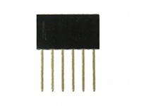
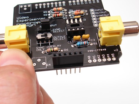
Female headers: it’s time to solder all of the female headers into place. The tricky part is getting them to stay aligned properly while you solder them on the bottom of the board.
Place one of the 6-pin female headers into position. Use some tape to hold it in place — make sure it is vertical.
Turn the board over and solder it into place. I ususally start by soldering only one pin, then check to make sure the header is positioned correctly. If not, I gently heat the one pin again, and adjust the position of the header.
Step 9
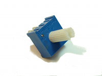
Insert the potentiometer with the long shaft into position in the upper left corner of the board. There are 4 holes in the board, but only 3 pins on the pot, so use the holes that have the same alignment as the pot (the board is designed to accomodate pots with different pin spacings).
Bend the pins on the bottom of the board so that the pot stays flat against the board. Turn the board over and solder.
Turn the pot to its lowest position (counter-clockwise).
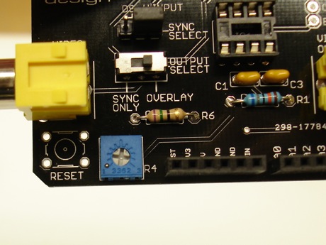
Step 10
Insert the small potentiometer into position R4 in the lower left corner of the board. Using a small screwdriver, turn the pot to its lowest position (counter-clockwise).
Bend the pins on the bottom of the board so that the pot stays flat against the board. Turn the board over and solder.
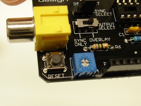
Step 11
Insert the small tactile reset button into the lower left of the board. It should snap into place easily.
Turn the board over and bend the tabs down toward the board so they lay flat.
Solder it on the underside of the board.
Step 12
Now it’s time to insert the LM1881 IC into the socket. ICs can be sensitive to static electricity, so touch something grounded to ensure that you don’t have static electricity charge built up in your body. For example, a metal pipe or the screw on a electrical outlet wall plate.
The pins on ICs are pointed outward from the chip a bit so we need to bend them inward so it will fit into the socket. Carefully bend the IC pins inward a bit by holding the chip against a flat surface.
When both rows of pins are bent inward, carefully insert the IC into the socket. Ensure that the notch on one end of the IC is aligned with the notch on the end of the socket. Apply gentle pressure until the chip is seated in the socket.
Step 13
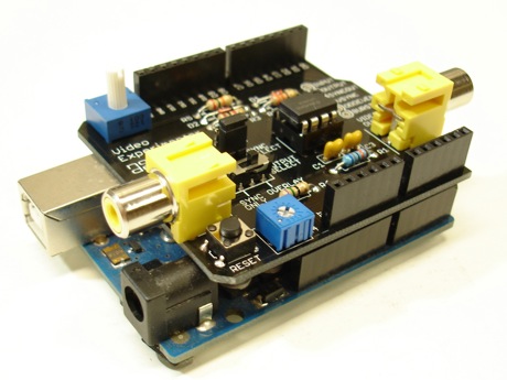
Bask in the glory of your success and have a beer. If you don’t drink or are too young to drink, have a piece of candy or something. Learn how to use the Video Experimenter on the projects page and start thinking about what project you will invent!
Troubleshooting
If you’ve assembled the Video Experimenter and it doesn’t seem to work, let’s ask ourselves some questions:
- Are you sure you’ve soldered everything together correctly? Double check your soldering to make sure you have no short circuits. Use a multimeter to help you determine if everything is connected. You can refer to the schematic available on the design page.
- Have you tried adjusting the potentiometers? R4 should usually be set to its lowest position. If you have vertical jumpiness, increase R4 a little bit.
- If you use a television with the PAL standard (that is, you are not in North America), your Arduino sketches will need to initialize the TVout library for PAL instead of NTSC. change lines like tv.begin(NTSC, W, H) to tv.begin(PAL, W, H).