Overview and Setup
The Game Timer Pro is a very flexible device and can be used as a sophisticated game timer or as an ordinary alarm clock (just like the original Defusable Clock product). When used as a game timer for escape rooms or airsoft/paintball competition, you have complete control over which wire defuses the device and which causes it to detonate. You can even pause or speed up the countdown. You can also require that a code be entered on a keypad to defuse it, or require that the wires be disconnected in a particular order. External devices like sirens or smoke grenades can be triggered on detonation or defuse. All configuration options are described in the configuration section below.
First connect the wires: Strip the insulation off of the end of 4 wires. Connect each wire to a terminal on the left side of the clock and to a terminal on the right side. It does not matter which terminals are used. All terminals on the left side are the same (connected to ground).
Then connect power. The recommended power source is a 9V adapter. The plug must be a standard 2.1mm power plug, and the center conductor should be positive. You can also power the Game Timer Pro with batteries, for portable use. We sell a 6xAA battery holder that comes with the power plug.
Using as a Countdown Timer
When the timer countdown is displayed and the countdown is not running, the left and right buttons are used to increase/descrease the countdown duration. After holding a left/right button for a few seconds, the rate of change will become much faster.
The default wire settings are: one randomly selected wire defuses the clock, one randomly selected wire causes immediate detonation, and two wires have no effect. This can all be changed by configuring the device as described below.
To start the countdown, press the red button. When successfully defused, the countdown stops. Press the red button again to exit the countdown. After detonation, the countdown stays at 00:00 until the red button is pressed again.
Using as an Alarm Clock
When the current time is displayed, the left and right buttons are used to change the current time. After holding a left/right button down for a few seconds, the rate of change will become much faster. When setting the time, the red LED on the left side of the board indicates PM.
To use as an alarm clock, set the display mode to show the current time and set the alarm time as described below in the configuration section. Also set the alarm mode to “beep” or “defuse”. “Beep” mode is just like a normal alarm clock. When the alarm is sounding, press the select button to turn it off. (The alarm will still be set for the next day.) To activate a 9-minute snooze alarm, press the red button. If the alarm is in “defuse” mode, the countdown timer will start and you will have a very rude awakening. This is an awful way to start your day.
Quick Instruction Videos
How to assign roles to the wires
How to set defuse wire order
How to set the alarm
How to use a keypad
How to connect a relay
How to use low power mode
Configuration
The Game Timer Pro has configuration menu that is easy to use. The 3 buttons above the display are used to navigate the menu, and the red button is used to exit the main menu or a submenu. Press the SELECT button (middle button) to enter the main menu. Use the left and right buttons to switch between each menu item. For example, the first menu item displayed is “dISP” to set the display mode. To exit the main menu, you can always press the red button.
To set the value for a particular menu item, press SELECT again to enter the submenu of possible values. The current value will be displayed, and you can use the left and right buttons to switch between possible values. When you are in a submenu, the LED at the top of the board is lit. To choose the displayed value as the new value, press SELECT, and you will be brought back up to the main menu. If you wish to exit the submenu without changing anything, press the red button. When you exit the top level menu, all settings are saved in non-volatile memory, so all configuration is remembered even when power is disconnected.
Below is a list of all the menu items and the submenu of possible values. Some menu items do not have a submenu, but allow you to set a numeric value. Don’t be afraid to play with the settings, because you can always reset to the default factory settings described below.
Diplay mode: determines whether the countdown timer is displayed or the current time.
Display the countdown timer.
Display the current time. This is used if you want to use the device as a clock.
24 hour time format
Display times using 24-hour format. e.g. 15:00 for 3:00pm
Display times in 12-hour format.
Alarm time. Use left and right buttons to set the alarm time. If time display is in 12-hour format, the LED on the left side of the board indicates PM when setting the alarm time. The alarm will be activated even if the display mode is set to countdown timer.
Alarm mode
Alarm is off
Alarm will beep like a normal alarm clock.
Defuse mode: when the alarm goes off, the countdown will start, beginning at the current countdown value.
Tick: enable ticking sound during countdown.
Countdown timer ticks every second
Countdown timer is silent
Detonation wire. This determines which wire causes detonation when cut.
No wire causes detonation when cut.
A random wire is selected when the countdown is started.
Set the detonation wire to wire 1, 2, 3, or 4. Wires are numbered left to right on the right set of terminals. If a wire is already assigned another role, it will not be available to choose.
Defuse wire or method to defuse. This determines how to defuse the device.
A random wire is selected as the defuse wire when the countdown is started.
A 4-digit code must be entered on a keypad (add-on package) to defuse the device. When this value is selected, you are prompted to enter the code on an attached keypad.
The wires must be cut in a particular order to defuse. When this value is selected, you are prompted to enter the wire order. Use the left and right buttons to increase/decrease the wire number (1-4) that must be cut first, then press select. Continue until all 4 wires have been specified. Other wire assignments will be ignored in this defuse mode.
Set the defuse wire to wire 1, 2, 3, or 4. Wires are numbered left to right on the right set of terminals. If a wire is already assigned another role, it will not be available to choose.
Double speed wire. You may set a wire that causes the countdown to speed up to double speed.
No wire causes countdown to speed up.
A random wire is selected when the countdown is started.
Set the double speed wire to wire 1, 2, 3, or 4. Wires are numbered left to right on the right set of terminals. If a wire is already assigned another role, it will not be available to choose.
Pause wire. You may set a wire that causes the countdown to pause for 2 seconds and then resume.
No wire causes countdown to pause.
A random wire is selected when the countdown is started.
Set the pause wire to wire 1, 2, 3, or 4. Wires are numbered left to right on the right set of terminals. If a wire is already assigned another role, it will not be available to choose.
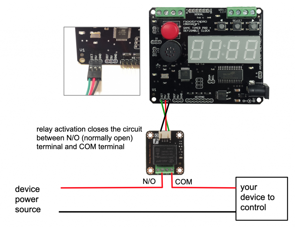
Detonation trigger duration: Set the number of seconds for the external detonation trigger. At detonation, the pad labeled “DET” at the bottom left corner of the board will be set to 5 volts for this duration. This is useful to trigger a relay to control an external device like a siren.
Defuse trigger duration: Set the number of seconds for the external defuse trigger. Upon successful defuse, the pad labeled “DEF” at the bottom left corner of the board will be set to 5 volts for this duration. This is useful to trigger a relay to control an external device.
Success code: set a 4 digit code that will display when the device is successfully defused. Use the left and right buttons to increase/decrease the first digit of the code, then press select to set the digit. This advances the next digit. Repeat until all 4 digits are specified. To clear an existing success code, hold SELECT then press red button to exit.
Brightness: set the brightness level of the display. Valid values are 1-16.
Sound level
High volume
Low volume
No sound
Low power mode
Normal power consumption
Low power mode when red button is pressed and held. This is useful when the device is enclosed in a box and an external switch is used to activate the countdown. When the switch is closed, the display is turned off and the device is in low power mode until the switch is opened again, causing the countdown to begin.
Factory Reset
You can always set the device back to the default factory settings: disconnecting power, press and hold the left and right menu buttons, then reconnect power. You will hear 2 beeps indicating that the device has been reset to default factory settings.
Connecting a Keypad
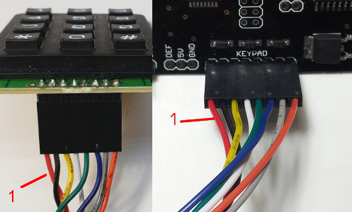
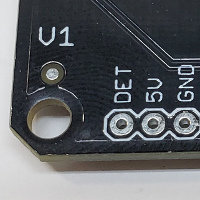
Connecting the keypad is easy but depends on which version of the Game Timer Pro and keypad you have. In May 2020, we started shipping a different keypad which requires version 1.1 of the Game Timer Pro board. The Game Timer Pro versions 1 and 1.1 are identical in every way except for the keypad they support.
If the keypad looks like this, it was shipped with a version 1.1 board. Connect it as shown.
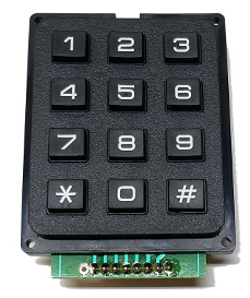
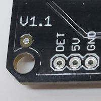
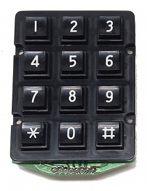
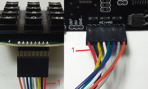
If your keypad looks like this, it was shipped before May 2020 and works with the version 1.0 board. You must connect the leftmost pin on the board to the rightmost pin on the keypad. So your cable needs a half twist.
Using the Infrared Remote Control
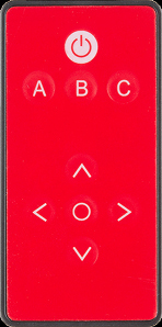
If your remote looks like this, when the countdown is displayed but not running:
- LEFT and RIGHT buttons: decrease/increase the countdown value
- CENTER button: start the countdown
While the countdown is running, you can control the countdown from a distance! The buttons have these effects:
- UP button: speed up the countdown to double speed
- DOWN button: set countdown speed to normal speed again
- A: Pause the countdown. Press A again to resume the countdown.
- B: Defuse the device
- C: Detonate the device immediately
After the detonation or defuse sequence, the center button can be used to reset the timer.
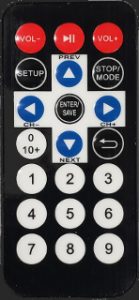
If your remote looks like this, when the countdown is displayed but not running:
- LEFT and RIGHT buttons: decrease/increase the countdown value
- CENTER button “ENTER”: start the countdown
While the countdown is running, you can control the countdown from a distance! The buttons have these effects:
- UP button: speed up the countdown to double speed
- DOWN button: set countdown speed to normal speed again
- 1: Pause the countdown. Press 1 again to resume the countdown.
- 2: Defuse the device
- 3: Detonate the device immediately
After the detonation or defuse sequence, the center “ENTER” button can be used to reset the timer.
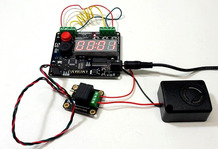
Connecting a Relay
A relay is an electronically controlled switch that lets you close (or open) a circuit when the timer is defused or detonates. This lets you activate an external device such as a siren, smoke grenade, audio player, etc. There are 2 connections on the Game Timer Pro, one for activation at detonation (DET) and one for activation at defuse (DEF). Connect a relay to the Game Timer Pro board so that the relays 5V trigger is connected to the left pin (shown as green wire).

